


A COMBINED LORRY AND TRACTOR UNIT.
Page 24
If you've noticed an error in this article please click here to report it so we can fix it.
A Resume of Recently Published Patent Specifications.
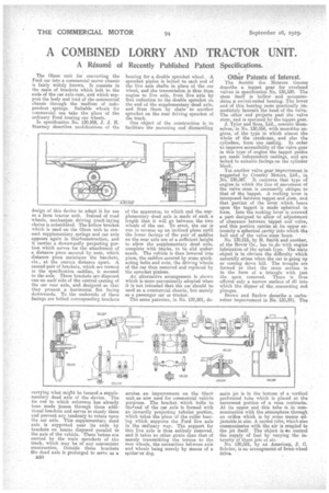
The Olson unit for converting the Ford car into a commercial motor chassis is fairly widely known. It consists in the main of brackets which :bolt to the ends of the car axle-case, and which support the body and load of the commercial chassis through the medium of independent springs. Suitable wheels for commercial use take the place of the ordinary Ford touring car wheels. In specification No. 130,508, J. S. H. Sturmey describes modifications of the
design of this device to adapt it for use as a farm tractor unit. Instead of road `wheels, mechanism driving track-laying chains is substitiked. The hollow bracket which is used on the Olson unit to connect supplementary springs and car axle appears again in this4censtruction, and it carries a downwardly projecting portion which serves for the attachment of a distance piece secured by nuts, which distance piece maintains the :brackets, etc.' at the correct distance apart. A second pair of brackets which are termed in the specification saddles, is secured to the axle. These brackets are disposed one on each' side of the central casting of the oar rear axle, and designed sothat they present a .horizontal flat facing downwards. To the underside of these facings are bolted corresponding brackets carry ng what might he termed a supplementary dead axle of the device. The tie rod to which reference has already been made passes through these additional brackets and serves to steady them and prevent any tendency to rotate upon the car axle. This supplementary dead axle is supported near its ends by brackets on beams disposed parallel to the axis of the vehicle. These beams are carried by the main sprockets of the track, which may be of any convenient construction. Outside these brackets the dead axle is prolonged to serve as a
850
bearing for a double sprocket wheel. A sprocket pinion is bolted to each end of the live axle shafts in place of the car wheel, and the transmission is thus from engine to live axle, from live axle by first reduction to the double sprocket on the end of the supplementary dead axle, and from there by chain to another sprocket on the rear driving sprocket of the track.
One object of the construction is to facilitate the mounting and dismantling of the apparatus, to which end the supplementary dead axle is made of such a length that it will go between the two wheels of the car. To erect, the car is run in reverse up an inclined plane until the lower facings of the pair of saddles on the rear axle are of a sufficient height to allow the supplementary dead axle, complete with tracks, to be slid underneath. The vehicle is then lowered into place, the saddles secured by some quickacting bolts and nuts, the etriving wheels of the car then removed and replaced by the sprocket pinions.
An alternative arrangement is shown which is more conveniently adopted when it is not intended that the car Should be used as a commercial chassis, but merely as a passenger car or tractor.
The same patentee, in No. 130,501, de
scribes an improvement on the Olsoti unit. as now used for commercial vehicle purposes. The bracket, which bolts to theffend of the car axle is formed with an inwardly projecting tubular portion, which takes the place of the roller bearing which supports the Ford live axle in the ordinary way. The support for this live axle is thus entirely removed, and it takes no other strain than that of merely transmitting the, torque to the rear wheels, the connection between axle and wheels being merely by Means of a spider-or dog.
Other Patents of Interest.
The Societe des Moteurs Gnome describe a tappet gear for overhead valves in specification No. 130,530. The stem itself is hollow and accommodates a swivel-ended bearing. The lower end of this bearing rests practically immediately beneath the head of the valve. The other end projects past the valve stem, and is operated be the tappet gear. J. Tylor and Sons, 1,(d., concern themselves, in No. 130,554, with monobloc engines, of the type in which almost the whole of the crankcase, and also the cylinders, form one casting. In order to improve accessibility of the valve gear in this type of engine the tappet guides are made independent castings, and are bolted to suitable facings on the cylinder block.
Yet another valve gear improvement is suggested by Crossley Motors, Ltd., in No, 130,387. It concerns that type of engine in which the line of movement of the valve 'stem is necessarily oblique to that of the tappet. A rocking lever is interposed between tappet and stem, and that portion of the lever which bears upon the tappet is made spherical in form. Into the rocking lever is screwed a part 'designed to allow of adjustment of clearance between tappet and valve, and this portion carries at its upper extremity a spherical cavity into which the ball end of the valve stem bears.
No. 130,515, by H. Smith and another, of the Rover Co., has to,do with engine lubrication of the splash type. The main object is to obviate the difficulty which naturally arises when the car is going up or coming down hill. The troughs are formed so that the cross section is in the form of a triangle with lust the apex removed. There is thus offered only a narrow surface of dil into which the dipper of the connecting rod plunges. Brown and Barlow describe a. carburetter improvement in No. 130,395. The
main jet is in the bottom of a vertical perforated tube which is placed at the narrowest portion of a vena contracta. At its upper end this tube is in communication with the atmosphere through an orifice which is by some means adjustable in size. A second tube, which also communicates with the air is coupled to the jet itself. The object is do control the supply of fuel by varying the intensity of these jets of air. No. 130,531, by an American, J. C. Scheler, is an arrangement of front-wheel drive.