


Patents Completed.
Page 20
If you've noticed an error in this article please click here to report it so we can fix it.
Tractor Clutch Mechanism. Improved Transmission Gearing. Another Carburetter. Tubular Wheel Construction.
Copies at complete specifications of the patents published on this page can be obtained from the Sales Branch, Patent Office, Holborn, WC., at the cost of sixpence for each specification.
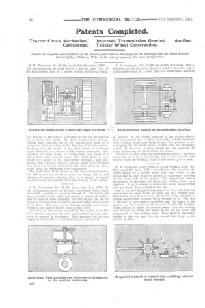
E. F. NORELIUS, No. 24,150, dated 16th December, 1914.— The accompanying drawing shows a partial plan view of the transmission gear of a tractor having self-laying tracks.
The steering of the vehicle is effected by varying the relative speeds of the two tracks. The drive is taken from a longitudinal shaft through one of two bevel-who:21s loose on a transverse shaft according to the direction of travel required. Working from the centre of the shaft, there is a driving pinion mounted on a sleeve which extends outwards. Surrounding this sleeve there is a bralre-drum, and beside it a clutch-drum with internal shoes. The brake-drum is connected to a spider in the clutch-drum through a gear permitting slight relative rotation, and the spider is so arranged that when it is turned relatively to the clutch-drum the shoes in the latter are withdrawn from engagement.
The application of the brake to the brake-drum therefore first disconnects the clutch -so that it no longer drives, and subsequently exerts a braking effect so as actually to retard the mechanism and thereby effect the steering of the vehicle.
J. L. CLOUDSIEY, No. 16,794, dated 14th July, 1914.—In this .carburetting device the air inlet is provided with a valve plate with S, number of openings through it. The fuel is fed into a channel in plate and passes by means of shallow slots to each of these openings. On the engine side of the opuings there is fixed an annular sheet of metal which covers al of thm. This sheet is cut through radially and is supported at one end so that it forms a flan valve.
According to the suction exerted bv. the engine, so is this valve drawn. away from the valve plate and the air-inlet apertures are opened in succession. Each aperture has its own supply of fuel so that a constant mixture is maintained.
J. R. CHURCHILL, No. 23,018, dated 25th November, 1914.— According to this invention the drive is taken from the engine and propeller shaft by a bevel gear to a countershaft mounted in bearings on the chassis forward of the driving-wheels. This countershaft may be fitted at its ends, outside the frame with winding drums and brake drums; this position is advantageous for the brake drums in that they are effectually cooled. If, however, winding drums are not required the brake drums may be fitted inside the frame. The drive is taken from the countershaft through a sprocket connected to it by a dog-clutch, and a chain to the rear wheels where the ordinary form of differential gear is used.
E. H. JONES and LICATrT STEEL TUBULAR WHEELS, LTD., No. 8937, dated 8th April, 1914.—According to this invention the centre flanges of a tubular steel wheel are welded to the spokes and to each other to provide a water-tight covering for the inner ends of the spokes. This specification relates particularly to apparatus for electrically welding these parts together. A jig 1,4 shaped to receive the wheel spokes which have previously been welded to the rim.
One of the hub flanges is then placed on top, and electrical connections are made to the jig itself and to a welding tool. This tool is carried on a lever, the handle being arranged to permit considerable pressure -tieing exerted on it. The face of the tool is very narrow compared with the length of the spokes, and it is water-cooled so as to localize the heating. When contact is made the current passes from the welding tool through the flange and spoke to the jig and raises the temperature to the welding point. Each spoke is separately welded in this way and then the second hub flange is also secured in place.