


SIX CYLINDERS FOR A HEAVY-DUTY CHASSIS.
Page 21
Page 22
Page 23
If you've noticed an error in this article please click here to report it so we can fix it.
Yet Another Example of the Growing Tendency to Use the Advanced Type of Engine.
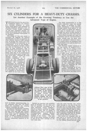
rr HE trend towards the use of six cylindered engines for commercial vehicles designed to carry heavy loads finds a new exponent in Walker Brothers (Wigan), Ltd., of Pagefield Works, Wigan, inasmuch as the new Pagefield chassis, for loads of six-seven tons, of which this Is the first published description, is so equipped.
The design of this new model is orthodox as regards its general specification, as will be apparent by what follows, which is only another way of saying that sound and welltried principles are embodied in its construction. It is in the details— in those fine points of design—which can only be developed as the outcome of long experience, that it shows itself to be really new and up to date, in the sense that it is better than any of its predecessors of the same name, good though they may have been. Perhaps the most obvious feature of the chassis, considered as , a whole, is the importance which has been attached to provision for economical maintenance, by mating all the essential parts accessible. Numerous examples of this are evident, but, in passing, we may quote the fact that it is possible to decarbonize the engine in an hour, from start to finish, notwithstanding its six cylinders, and that the brake shoes are accessible for relining without removing the hubs.
The general specification embodies a six-cylinder Dorman engine of 100 ram. bore and 140 mm. stroke. The clutch is a multi-spring fabriclined _cone and It transmits the power through a doubly-articulated shaft to a four-speed-and-reverse gearbox, separately mounted in the chassis.
Behind the gearbox, the propeller shaft is divided, and the rear portion is partially enveloped in an open cast-steel torque member— this is a feature peculiar to Pageflelds—the front end of which is spherical and takes a bearing in a correspondingly shaped bracket mounted on a substantial crossmember of the frame. The rear end of the torque member is bolted to one of the steel castings on the rear axle case. The final transmission is of the double reduction type ; the design here, again, is peculiar to Pagefields, embodying a first reduction through, spiral bevel gears, to the crown wheel of which the differential gear is bolted, and a second through two pairs of spur wheels to the live axles and rear road wheels.
Semi-elliptic springs are used for suspension and the cast-steel hollowspoke wheels may be shod with solid or pneumatic tyres at choice. The vehicle which we examined was on pneumatic tyres and we shall deal with that type.
The Dorman engine employed is the one known as model 6 J.U.L. Mark 2. The R.A.C. rating is 37.2 h.p. Actually, it develops 40 h.p. at 800 r.p.m., 48.5 h.p. at 1,000 r.p.m. 73 at 1,600 r.p.m. and 80 at 2,000 r.p.m. The six cylinders are cast together, the makers claiming that one of the several advantages of this construction is that the engine is thereby rendered more rigid because of the additional stiffness which is imparted by , this substantial casting.
The crankcase is of aluminium throughout, but to ensure that no stress is taken by this metal the bolts which hold the main bearing are taken right through to the top of the casing and are of nickel steel. There are four main bearitigs to the crankshaft, which Is fitted with a vibration damper and spring pinion to ensure smooth running at all speeds. The connecting rods are of duralumin and the pistons of cast iron.
The valves are disposed side by side and it is worthy of note that, in this engine, spur gears are used for the timing wheels and not silent
chains. The cooling water is pumpcirculated, the pump being driven by a cross-shaft at the other end of which is the magneto, which is thus particularly accessible, inasmuch as the contact breaker faces outwards and can be reached at once on lifting the bonnet.
The engine lubrication system is force feed positive and automatic. A large gear-type oil pump is located at the lowest point of the smnp, being driven by spizal gearing from the crankshaft. This pump forces the oil to each main bearing and camshaft bearing. There is a large strainer on the suction side, so placed that all solid matter is prevented from entering the pump, impurities so separated collecting in a well which can easily be cleaned on removing a plug specially provided for the purpose. A second filter is fitted on the suction side of the pump as an additional safeguard and this, too, can be removed and cleaned without losing any oil. Constant pressure is maintained in the whole system, ensuring a regular and sufficient supply of lubricant to each bearing. There is a relief valve, which is set to control the pressure to from 12 lb. to 15 lb. per sq. in. and any surplus passes to the timing wheels and magneto driving gear. The sump holds three gallons of oil and there is an indicator to show the depth of lubricant therein.
The carburetter is a Zenith and the magneto a Simms. The latter Is driven through a coupling which combines a positive drive with a fine adjustment, the latter being so contrived that whilst the timing can easily be altered once set it cannot slip. The ignition control is automatic.
A feature of the exhaust pipe n38 arrangements is that provision is made in the fixing of the exhaust manifold to allow for expansion and contraction as the temperature changes.
As has already been stated, the clutch is of the cone type, fabriclined. It is controlled by three light coil springs, very easily accessible for adjustment and the design is interesting inasmuch as it embodies an unusually large ball thrust bearing located round the boss on the flywheel. The pivot bearing is large and long and grooved to facilitate lubrication. The whole of the doubly articulated clutch shaft moves to and fro as the clutch is manipulated and a clutch stop is mounted on that shaft to facilitate gear changing.
The gearbox provides four speeds forward and reverse, and a feature of its construction is the provision of additional bearings midway along each shaft. The object of this is to eliminate the possibility of whip. In this box the second, third and fourth speeds, as being the ones most generally used, are constantly in mesh, engagement being effected by means of dog clutches. The first and reverse speed wheels are of the ordinary sliding type.
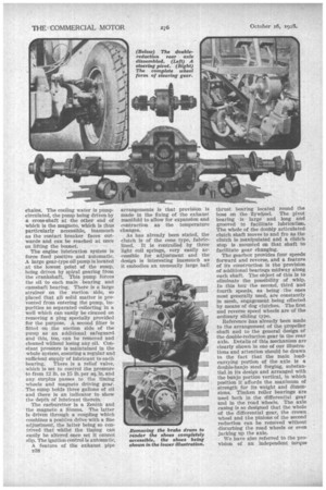
Reference has already been made to the arrangement of the propeller shaft and to the general design of the double-reduction gear in the rear axle. Details of this mechanism are clearly shown in one of our illustrations and attention should be drawn to the fact that the main loadcarrying portion of the axle is a double-banjo steel forging, substantiaLin its design and arranged with the banjo portion vertical, in which position it affords the maximum of strength for its weight and dimensions. Timken roller bearings are used both in the differential gear and in the road wheels. The axle casing is so designed that the whole of the differential gear, the crown wheel and the pinions of the second reduction can be removed without disturbing the road wheels or even jacking up the axle.
We have also referred to the provision of an independent torque member. For this to be operative, it follows that the axle casing must be free to rotate partially in spring brackets and these, as a matter of fact, are so designed as to form ample bearings upon journals formed on that axle; they also serve to carry the fulcra of the rear brakes.
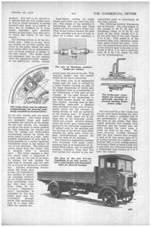
The braking system is of the sixbrake type. That is to say, there are brakes on all four wheels operated by the pedal, whilst the band lever takes effect on an independent pair of shoes mounted in drums in the rear wheel. (We would recall our statement that we are dealing with the pneumatic-tyred chassis; ou the solid-tyred vehicle, brakes on the rear wheels only are standard equipment.) The brake drums are unusually large and easily accessible for renewal of the lining. On the rear wheels, for example, access to the shoes is made possible by first removing the wheels and then by taking out half-a-dozen countersunk screws by which the drum itself is held to a hub. Independent adjustment of each shoe is made possible by a rather ingenious mechanism which is the subject of one of our sketches. The steel pad which bears upon the brake cam is integral with a screwed stem. The latter engages a split nut which itself is supported in a split boss at the end of the shoe. To adjust, the bolt holding the split boss is released and the split nut is rotated by means of a tommybar. Another interesting feature about the brake gear is that all cross-shafts are carried, in spherical bearings mounted on the frame members, thus preventing binding that may arise from whip of the f r a in e. Dewandre servo mechanism is embodied in the foot brake gear and the
cross-shaft through which this mechanism acts is a steel tube 244th ins, outside din.
Semi-elliptic springs of ample length and width are used fore and aft. The design of the shackles is interesting, the shackle pins being hollow but not screwed at either end. They do not project beyond the ends Of the shackles and each is held in place by a cotter bolt engaging a groove near the end of the pin. This reduces weight and the overall width of the parts concerned.
The front axle is of substantial design and the load is carried by a large Timken bearing, an idea of the large dimensions of which may be gathered from an examination of our illustration of this part of the chassis. In the same picture, the arrangement of the connections to the front brakes should be noted. The leather covering seen in that illustration enshrouds a Hooke's joint provided to take care of movements which are the outcome of spring flexion as well as operation of the steering gear. It should be noted that these joints are in the same line as the \stub-axle pivots, which are canted. Another feature about the brake gear connections in • general is the universal employment of splined ends to the spindles and the location of the levers upon those spindles by cotter bolts which engage circumferential grooves cut near the ends of the spindles.
The frame is a substantial pressed steel structure with many crossmembers and is strengthened by internal flitch plates, one to each side member, extending from near the rear spring rear shackle to the cor responding point of attachment of the front spring.
The following leading dimensions are of interest. The total length of the chassis is 23 ft. 8iins., the wheelbase being 15 ft. 0/ in., the track of the front wheels is 6 ft. 24 ins, and that of the rear wheels 5 ft. 8 ins. This model is of the forward dash type, affording ample body space behind the dash. Actually, the measurement from the back of the driver's seat to the end of the frame is 19 ft. 1 in. and a platform body 19 ft. by 7 ft. inside the sills can be accommodated.
Our own arrival at the "rorks was not too well timed because we were unable -to make a personal test of the performance of this chassis. The first of the series, that illustrated herewith, had already been delivered and the second had not quite reached the state when it could be tried on the road. We were, however, credibly informed that the first chassis thad brought a load of 21 tons gross—part of it, of course, carried on a trailer—over Parbold Hill, a local testing ground involving a climb of about a mile and a half with two awkward bends and a moderately long stretch of 1 in 7 near the summit.