


Power--assisted Trailer
Page 58
If you've noticed an error in this article please click here to report it so we can fix it.
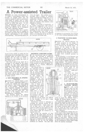
THERE are many circumstances in which a tractor-drawn trailer may become so bogged down that the tractor is unable to shift it, particularly when loads of timber, beet or other crops are being moved from the rough around in which they grow. To suit these circumstances is the aim of •a specially designed trailer shown in patent No. 650,335, by P. Holmqvist and others, Bjarsater, Sweden.
The proposed trailer has a powerdriven axle which can be coupled to the power take-off of the tractor and so become self-assisting if not actually self-propelling. The drawing shows the
layout of the vehicle, in which the live twin-tyred axle is provided with a long . propeller shaft (1) and, if desired, a gearbox (2), the lever of which is extended to come within the reach of the tractor driver.,
The front end of the shaft (3) is arranged to be joined to the power take-off by the -usual quick-action coupling. Another point of the patent dears with the result of the close coupling of the tractor and trailer; when turning it is possible that the tractor tyres would make contact with the trailer, and so the latter is fitted with free-running rollers at the points of likely contact A NEW PRINCIPLE IN ENGINE COOLING
PATENT No. 650,334 shows a cooling system employing liquid as a coolant, but without the usual piping and radiator, these being replaced by fins on the cylinder. Although probably originally intended for aircraft engines, the principle has possibilities for other types of power unit. The patentee is D. Pobjoy, -Box Farm, Woodmancote, Cheltenham.
The drawing shows the scheme applied to the cylinder of an overhead.
valve oil engine. The cylinder,head is provided with a jacket or chamber which surrounds the hottest part of the combustion chamber. The jacket is filled with a special liquid; suitable types are benzene, ethyl alcohol, ethyl chloride or toluene.
Water, it is slated, is unsuitable, as its critical temperature and pressure (374 C. and 3,200 lb. per sq. in.). are far too high. In action, the liquid surrounding the hot spot circulates round the comparatively cool walls of the jacket, whence the heat is conducted away to be disposed of by the fins as in a normal air-cooled unit.
METERING INJECTION PUMPS
1N the conventional type of injection pump, the metering is performed under full injection pressure. which calls for accurate fitting of the parts, if leakage is to be eliminated. A pump in which the metering is done at. a low pressure in shown in patent No. 650,028. by L. French, Milwaukee, Wisconsin, U.S.A.
The scheme refers to the individual type of .pump which is fitted one to each cylinder, and the drawing shows a section of such a unit. In this design, the central plunger (I) is stationary, and the pumping is performed by the ascent of the surrounding barrel (2).
This is fitted with piston-rings and is lifted against a spring (3) by the compression in the cylinder. It is provided with a conical seating (4) at the bottom, so that at the moment it lifts, the compressed air rushes in and acts on the larger area offered by the shoulder (5) so that a snap action is obtained.
Quantitative control is afforded by arresting the upward motion of the barrel hydraulically. Upper space 6 is full of fuel, and as the barrel rises some of it spills into the supply port (7). This port is controlled by a conventional helical edge (8) worked by an external lever (9) • By varying the quantity of fuel trapped in the upper space, the lift of the barrel, and the displacement in the working space. are controlled. As this fuel is at a comparatively low pressure (100-300 lb. per sq. in.) the sealing problems are reduced. The total time A MAGNETIC CLUTCH FROM FRANCE
PATENT NO. 650,174 discloses the latest progress in the design of magnetic clutches, the patentee being S. A Francaise du Ferodo, Paris. A feature of the clutch is that the magnetism is used, only to free the plates, the driving force being obtained from springs in the usual way. In fact, the main aim of the design is to depart as little from standard practice as possible.
In the drawing I is the flywheel and 2 the spring-loaded presser-plate. The single driven disc (3) is gripped between the two and-is slidably splined on the output member. The annular magnetic winding can be energized via the brush and slip-ring (5), and its pull overcomes the force. of the springs and frees the driven plate in the same manner as a conventional pedal-operated clutch.
A point not made clear in the patent i! how the current can be switched off to give gentle engagement; sc far as could be seen i would result in a jerk.
A PUNCTURE-PREVENTING DEVICE AANY and varied IVI have been the suggestions in the past for the prevention of punctures, and even now the ingenuity ol inventors has not been exhausted. The latest proposal comes in patent No. 649,191, from L. Rundle, 38, Walnut Road, Torquay.
This inventor suggests the use of a thin rubber protective strip to be placed between the tube and the outer cover. Such a scheme is by no means new, but the present invention goes a little further by using the strip to eject small sharp objects before they have time to cause a puncture.
This is achieved by making the protective strip a little longer than its true circumference should be which means that when in place there is a little pucker at one point. During running, • the pucker slowly creeps round and sets up the working-out action which brings about the ejection mentioned.