


Hydraulic Coupling With Low-speed Slip
Page 45
If you've noticed an error in this article please click here to report it so we can fix it.
.A N hydraulic eoupling, which will .1""1 perform the duties usually associated with an automatic centrifugal clutch, forms the'subjeCt of patent No.
506,839., from s. liydra,ulic Control Engineering Co., Cleveland, Ohio, U.S.A. Incorporated in a vehicle transmission; it would transmit no drive at idling speed, but increasing the engine speed would bring progressive take-up up to a complete straight-through slipless drive.
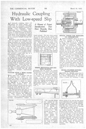
• Referring to the drawing, the driven shaft (1) 'carries the complete outer casing including an internal gear-ring (2), The whole of the internal mechanism is connected to the input shaft (3). The interior consists of a cylindrical body cut away to house a pair of pinions which, in conjunction with the gear-ring, form ,a pair of gear pumps. Their fluid path is a complete circuit, and includes a small port' (4) in a spring-loaded sliding valve.
In action, at idling speed, the whole of the fluid flow can pass freely through the port (4) and 100 per cent, slip takes place. With an increase in speed, however, the fluid pressure rises, and the reaction tends to transmit a torque of increasing value. Under full load, the spring-loaded valve is forced over to the right, in which position the small , leak. port is covered . and the whole mechanism becomes hydraulically ' locked.
TRACTOR WITH A WIDE RANGE OF SPEEDS
THE usual type of tractor with its unsprung rear wheels is. very limited in respect of high-speed road work, and an effort to improve matters' in this respect is shown in patent
• No. 566,496 by .0. Bernhard, -187,
• Maida Vale, London, W.9. -This Inventor proposes to. increase the speed • range by extra gearing and to add a ' springing system for the rear axle. The drawing shows that part of the machine to the rear of the gearbox. A torque tube leads to the primary axle (1) which. contains the differential gear. The drive is then „divided between a pair of two-stage chain-andsprocket transmissions housed in closed casings. The first chain system (2) i the essence 'of the patent; this consists of two sprockets of unequal size which can be transposed to give a considerable. alteration of total reduction. When small drives large, a low gear is available for the heaviest of agriculturar operations, hut with the large driving small, a high road speed, up to 40 m.p.h., may be obtained. To facilitate the change-over of the sprockets, both they and their housing are fitted with quick-detachable fixings.
SPRING MOUNTINGS FOR BUS BODY BEARERS
COACH and bus bodies are usually 1,—,Mounted on a number of transverse bearers laid across the frame, which, as the result of continued operation over rough roads, are prone to develop cracks. • To avoid this and ' other troubles cauSed by road shocks is the object of a resilient mounting shown in patent No 566,855 by F. Rayer and Metropolitan-Cammell Carriage and Wagon Co., Ltd., Saltley, Birmingham, 8.
The 'drawing shows the essence of the proposals which call for the interposition of leaf springs between the body bearers and, the frame members. The springs are bolted to the bearers, and hooked around the chassis girders, . so that, whilst a certain amount of vertical freedom is permitted, the body is rigidly located in a sideways direction, SPECIAL PISTON FOR REDUCING OIL CONSUMPTION
AREPLACEMENT piston for use in worn zylinders is disclosed in patent No. 566,547 by J. W. Senior, 2, Hagg -Lane, Sandygate, Sheffield. The piston is claimed to reduce the excessive oil consumption which is usually experieficed in such eircumstances. Referring to the drawing, 'the cylinder is shown with greatly_ exaggerated wear at the point (1), near the upper end of the stroke. The proposed piston is made With a reduced diameter (2), which is the chief feature of the scheme. Whereas in a normal closefitting piston, the oil scraped from the cylinder walls on the compression stroke is, at "top dead centre, squirted into the combustion space and burnt, in the present instance it would be collected in the clearance (3), which is well out of the way of the combustion flame.
BRAKE CYLINDER RETURN. SPRING LOCATION
PATENT No. 566,933 comes from J. Pratt, Guildhall Buildings, Navigation Street, Birmingham, 2, and discloses a means for enabling a large
return spring to be used for the piston of, an hydraulic-brake master cylinder, The usual position, inside the cylinder, provides only limited space, and difficulty has been experienced in housing a sufficiently powerful spring.'
The problem is solved by locating the spring outside the cylinder, as shown in the drawing. The spring (1) is of V-outline and is fixed to one end (2) of the cylinder; at the other end it embraces the piston rod behind the operating pedal (3) . This end is slatted and fits a squared part of the piston rod to key the rod against rotation: this feature helps to prevent the driver's foot slipping off during operation.