


A Power-operated Tailboard
Page 48
If you've noticed an error in this article please click here to report it so we can fix it.
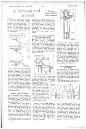
PATENT No. 599,841 refers to tail. boards for lorry bodies, whereby the board is used to lift loads from the ground to the level of the floor. The patentee is Gar Wood Industries Inc., Detroit, Michigan, U.S.A. With such devices, the limited space under the chassis calls for a compact mechanism, and the scheme described conforms to the requirement.
The drawings show the tailboard In its three operative positions; on the ground for loading (1), at body level (2) and in its uppermost position (3) in which it acts as a closure for the body. The power niember is an hydraulic barrel (4); this contains fixed and moving vanes which alter their angle when fluid under pressure is applied. The moving vanes are connected to arms (5) Which form the lifting members, and the link motion maintains the board in an approximately horizontal position. The board is• lifted into its uppermost position by hand, during which a screwed rod (6) slides out of its containing sleeve.
A NOVEL TYPE OF VEHICLE
LOW production cost, economy in running, and a pleasing appearance, are some of the virtues claimed for an unorthodox vehicle described in patent No. 599,000, by M. Alamagny, St. Cloud, France.
The oddest feature of the design is that the wheels are arranged in a diamond-shaped pattern, that is, one at the front, two in the centre and one at the rear. The middle pair convey the drive, the engine and transmission units being mounted close to them, crosswise in tilt frame. Steering is performed by the front and back wheels acting in unison through a common control.
Parallel-link suspension is employed, and no chassis proper is provided, the a33. body floor forming the main member. Access to the interior is obtained by swinging the body about a pivot into an open position, in a manner described in an earlier patent. No. 598,633. All the passengers sit with their backs to the engine, which means that the rear passengers are facing backwards. Other designs show a similar layout applied to a large vehicle having 12 wheels.
SIMPLIFYING THE MACHINING OF CYLINDER HEADS
PATENT No. 599,755 refers to oil engines having a combustion chamber machined in the head, and comes from John Fowler and Co. (Leeds), Ltd., and A. Howard, both of Leathly Road, Le'eds. The difficulty of machining a formed outline is mentioned, and the new design is said to be easier to produce, although retaining all the advantages of the machinedfrom-the-solid type.
The drawing shows a cylinder head in place on the cylinder; the combustion chamber consists of a plain parallel bore with a domed end (1). To create the desired shape, a steel cup (2), provided with a slot (3) to communicate with the cylinder, is placed in the bore. The cup is a much more simple piece to machine than would be a complex form in the cylinder head. Although the cup is keyed against rotation, it is otherwise an easy fit in is housing, so as to diminish heat-loss, which might otherwise occur, to the water-cooled head.
DESIGN FOR A DISC BRAKE IT is rather surprising that the disc
brake is not used on road vehicles, because it has several advantages over the conventional drum type. It is not distorted by heat, its friction members are simple flat rings, and the whole of the friction area is loaded uniformly when in use. A design for a brake of this type, suitable for a road vehicle, is disclosed in patent No. 599,541, by G. Roberts, The White Bull, Great Eccleston, Lancashire.
Referring to the drawing, the moving part consists of a two-piece enclosing shell (1) bolted into a unit which is attached to the wheel. Inside this is housed a pair of stationary discs (2) attached to the back-plate (3). In operation, the stationary discs are expanded axially and press the friction rings (4) on to the outer member. The separation of the two discs is performed by an interior mechanism which employs balls riding up inclined planes, a scheme which gives a self-energizing effect. The action is initiated by a pair of balls .(5) which are spread by a wedge member carried by rod 6.
AN ENDLESS TRACK BY SCAMMELL
ikDESIGN for an endless track of the locked girder type comes, in patent No. 599,515, from P Hugh, E. Davies and Scammell Lorries. Ltd., Tolpits Lane, Watford. The chief aim is to provide a large rigid groundengaging area at a moderate constructional cost.
The drawing shows a.plan view of a single link of the proposed track. A
pair of upstanding parts (I) form a prong which embraces the tyre and keeps the track to the middle of the wheel. The tread portion consists of six inclined pieces (2) fitted with hollow bosses (3 and 4). These are offset by one width of boss, so that each set can interleave with its adjoining link and be secured by a pivot pin inserted through the whole row. Portion 5, ahead of the pivot point, forms an abutment which prevents flexibility beyond the straight-line condition