


An Improved Axle for Trolleybuses
Page 44
If you've noticed an error in this article please click here to report it so we can fix it.
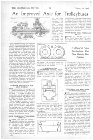
THE high motor-speed of a trolleyb.us calls for an axle reduction of about 10 to 1,' and this often tends to overheat the axle, particulady when electric braking imposes an additional load on the transmission. .To prevent this temperature, rise, the axle gears have to be made unduly large, a factor which ultimately results in a high floor-level and decreased ground clearance. To obviate these defects, by dividing the total reduction into two stages, is the object of an ,improved axle shown in patent' No. 566,331, by F. Cowell and Kirkstall Forge, Ltd., both of Kirkstall -Forge, Leeds, 5.
• Referring to the drawing, the propeller shaft drives a bevel pinion (1) which meshes with the usual crown wheel and gives an initial reduction in the order of 3 to 1. Each half-axle is fitted with spur-gear (2) which drives the internally toothed huh via a group of stationary planetary pinions, and thus the final reduction is achieved. No claim is made for the system on any • vehicle other than a trolleybus.
WEATHER PROTECTION FOR LEAF SPRINGS
THE conventional leaf spring has to work in all weathers, and is usually found to be covered with grit, dust and mud. A scheme to afford protection from such foreign agents forms the stibjeet of patent No. 566,377, from A. Kyle and Jonas Woodbear.1 and
• Sons: Ltd:, Kirkstall Road, Leeds. These inyeatorspropose to cover each leaf during manufacture with a plastic coMpound that will remain plastic at all normal temperatures.
• The coating' may be sprayed on, or pulled over in the form of a fashioned gaiter; in another scheme the spring is • enclosed as a whole, with no plastic between the individual leaves.
SNOW CHAINS FOR TWIN-AXLED VEHICLES
A SNOW chain that will convert a twin-axled vehicle into something resembling a track-layer forms the subject of patent No. 566,246, from D. Kennedy, Forest Works, Long-parish, Andover, Hants.
The drawing shows the proposed chain in place around the two driving wheels. It consists of side members which lie against the walls of the tyre, A84 side plates. The units thus formed are connected by chain links shown in broken line in the drawing.
A DOWNDRAUGHT CARBURETTER PETROL TRAP WHEN starting an engine from cold, W there is a tendency for liquid petrol to collect in the induction system, particularly when •a down draught carburetter is employed. To prevent this is the object of a scheme' shown in patent No566,295, by the Austin Motor Co., Ltd., and L. Kings, both of Longbridge Works, Birmingham. • The drawing shows part of...a, manifold in which I is the exhaust system and 2 the inlet. Immediately beneath the carburetter (3) is a small bore (4) which leads to a chamber formed above a copper partition (5). Any petrol descending from the carburetter drains into this chamber and is not carried into the cylinders. When the exhaust system warms up, the petrol is expelled again in the form of vapour. A small atmospheric vent (not shown) is also located in the chamber.
PISTON RINGS FROM POWDERED METAL
PATENT No. .566,385 comes 'from the British Piston Ring Co., Ltd., and others, Brico Works, Holbrook Lane, Coventry, and destribes methods
of forming piston rings from mixtures of powdered metal. 'The Chief feature of the patent is a means for 'varying the density of the finished :ring, according to the service to which 'it is subjected. •.
A mixture is described which can be pressed into Shape so as to give a density of fronf6.5 to 6 9, according to the , pressure employed; this varies between • 40 and' 60 tons per sq. in. The density is also dependent upon the temperature used in the sintering operation. Other metals may be alloyed with the iron, also graphite if a self-lubricating property be desired.
INCREASING THE RESILIENCE • OF PNEUMATIC TYRES
SOME interesting criticisms of the conventional design of the pneumatic tyre and its rim are contain'ed in patent No. 566,065, which comes from F. Baker, Oldswinford, Stourbridge, Worcs. This inventor states that, as the tyre is secured solidly to 'its rim base, it is in direct contact With a solid Metallic mass; 'Which reduces the available resilience. To increase the latter by providing a movable rim base is the. objectof his improved design'.
The drawing -shows a section of a rim embodying the improvements, It will be seen that the base-is forin-ed as a separate member; this is a band (1) surrounding 'the wheel, with a sliding joint, So that its circumferential length may vary. When the load is applied, the band can flex inwardly and so impart a measure of additional cushioning to the wheel-. Another scheme suggests the use of a second inner tube 10tated in space 2 between the band and the actual base of the rim.
The effect on lateral stability of such an arrangement might be to counteract the advantages gained in resilience.