


AUXILIARY
Page 44
Page 45
Page 46
Page 47
If you've noticed an error in this article please click here to report it so we can fix it.
BRAKING DEVICES
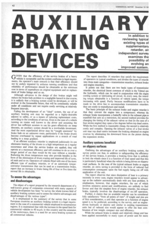
GIVEN that the efficiency of the service brakes of a heavy vehicle is acceptable and the system conforms to legal requirements, the operator's main concern is that their efficiency should not be unduly impaired by arduous running conditions and that reliability of performance should be obtainable at the minimum cost in terms of expenditure on original equipment and on replacement of brake linings and so on.
Although advances in the design of disc brakes might well reduce the brake-fade problem to a negligible hazard in due course, it is unlikely that a braking system could be developed, or will be evolved in the foreseeable future, that will be consistently reliable under all conditions and not require costly servicing at relatively frequent intervals.
Failing the development of an "ideal" system, the use of an auxiliary braking unit may be regarded as a highly-desirable adjunct to safety, or as a means of reducing replacement costs, according to the conditions of service. Even in the case of a vehicle running on routes well known to the driver and assuming the driver has sufficient acumen to use his gears effectively on steep descents, an auxiliary system should be a worthwhile investment. And the most experienced driver may be "caught unawares" by brake fade on an unknown route, particularly if the brake drums become overheated by repeat applications on a stretch of road leading to a steep gradient.
If an efficient auxiliary retarder is employed judiciously its use eliminates heating of the drums to a high temperature as a regular occurrence and when the service brakes are applied, they will operate at a maximum efficiency and will continue to do so over a longer period of use than would be the case without a retarder. Reducing the drum temperature may also provide benefits in the form of the elimination of drum crazing and improved life of tyres, oil seals and so on. Operators of vehicles fitted with one of the more efficient type of auxiliary retarder, or of an automatic torqueconverter transmission that can be used as a transmission brake, report that an increase in brake lining life of four or five times the normal life is obtainable.
To assess the advantages and disadvantages
The object of a report prepared by the research department of a well-known group of companies concerned with many aspects of vehicle development has been "to survey the whole known field of auxiliary braking systems and to assess the relative advantages and disadvantages of the various types".
It is emphasized in the summary of the survey that in some European countries an auxiliary braking system is a legal requirement in the case of a commercial vehicle employed in mountainous regions. It is maintained that with the increase in the speed limit for commercial vehicles to 40 m.p.h. in this country and the extension of the motorways, there is a need for an extra braking system on all commercial vehicles. The report describes 14 retarders that satisfy the requirement; of operators in typical conditions, and divides the types of retarde into three main categories—transmission retarders, exhaust brake and engine retarders.
It points out that there are two basic types of transmissior retarder, the electrical (most common of which is the Telma) am the hydraulic, which can be used in conjunction with the engint cooling system or lubricating oil circuit. In every case, the retarding torque obtainable is a function of vehicle speed, the torque increasing with speed. Partly because modifications have to be made to the drive line to accommodate transmission retarders. they are costly to manufacture and install.
The basic principle of the exhaust brake and engine retarder it that they convert the engine into a compressor; whereas the exhaust brake incorporates a butterfly valve in the exhaust pipe oi manifold that acts as a restriction, the second method provides for changing the timing of the exhaust valves so that (in the case of a four-stroke engine) they open a few degrees before top dead centre. While the first method is reasonably cheap, the second is relatively costly and complex. Opening the exhaust valves of a four-stroke unit near top dead centre increases the braking obtained on engine overrun by eliminating the downward force on the piston during the expansion stroke.
Auxiliary systems beneficial on slippery surfaces
Outlining the advantages of an auxiliary braking system, the survey points out that, in addition to safeguarding the efficiency of the service brakes, it provides a braking force that is unlikely to lock the wheels since it is a function of road speed and that this is particularly beneficial when the vehicle is being driven on slippery road surfaces. In the case of the typical exhaust brake or engine retarder, an extra saving is provided in the form of reduced fuel consumption consequent upon the fuel supply being cut off with application of the unit.
The report observes that since dissipation of heat is a primary necessity in every case, engine retarders would appear to advantage as the radiator automatically deals with any heat problem. It emphasizes, however, that engine retarders, the use of which involves extensive power-unit modifications, are unlikely to find favour and that the simplest form of engine retarder, the exhaust brake, typically involves the disadvantage of on /off operation.
Further, it claims that no available retarder can be considered fully satisfactory "from all points of view". If weight and size are of first consideration, a unit that operates as a function of engine speed is to be preferred, according to the survey, and an enginedriven hydraulic or electric unit similar to existing transmission units but of reduced size would appear to offer the best combination of low weight, compact size and efficiency.
While the exhaust brake is simple and relatively cheap and has • been applied successfully to many types of power unit for more than 10 years, whether or not its use can be injurious to the engine is debatable. It is considered appropriate, therefore, to comment on some of the controversial aspects of exhaust brakes that are not discussed in .the survey or are only mentioned briefly.
Disadvantages of the exhaust brake to which reference is made in the survey include the necessity, in some cases, to modify the exhaust valves and manifold to withstand the higher hack pressure (about 35/40 p.s.i.) involved. If the pressure is sufficient to
overcome the tension of the exhaust-valve springs it will open the exhaust valves of the "non-operative" cylinders that are not discharging into the exhaust manifold and engine makers are sometimes unwilling to modify or sanction modification of the springs to increase their rating.
In criticism of exhaust brakes, a well-known engine maker emphasizes that modification of an engine to cater for the higher back pressure is undesirable. If the tension of the exhaust-valve springs is increased a basic design principle of the engine is changed; if the valves open under the pressure created, the severe blow-back through the combustion chamber into the intake produces a roar that in the case of a bus or coach is disturbing to the passengers. Moreover, the blow-back of hot gases can also result in "dieseling" or compression-ignition of the lubricating oil and if the natural frequency of the springs matches the gas surge frequency or a harmonic, the life of the springs is greatly reduced. Additionally, blow-back increases valve-stem wear.
This maker has, however, produced special springs for the engines of p.s.v. fitted with exhaust brakes that were destined for export and his comments contrast with those of another maker (and of many operators) who claim that no service problems are created by the use of an exhaust brake given that it is applied to a suitable unit. According to the second maker no damage to the engine or increase in maintenance costs should result from employing a typical exhaust brake.
On the credit side, the survey further points out that in addition to the fuel-saving provided, engine temperature is maintained on a long descent, overspeeding of the engine is less likely and that inertia loading on the connecting rods during the exhaust stroke is reduced. A braking potential of 85 per cent of the engine power is given in the survey as a typical figure.
The different types available
Various types of exhaust brake are mentioned in the survey including a number of versions of the Oetika unit, the American Williams brake and the Ashanco, produced by Thomas Ash and Co., Ltd., 19 Rea Street, Birmingham 5, special mention being made of the types of control offered by the Clayton Dewandre Co., Ltd., Lincoln, for applications of the Oetiker units it produces. (Clayton Dewandre also markets a lightweight exhaust brake of its own design.) Electric brakes described in the survey comprise the Telma, marketed in this country by the Trico Developments Co. Ltd., of Brentford, Middlesex, the American Warner and the French Jourdain-Monneret. Hydraulic retarders to which reference is made include the Thompson, marketed by the Lockheed Hydraulic Brake Co. Ltd., Leamington Spa, and the American Hydrotarder. Two engine brakes are mentioned, the American Jacobs, marketed in this country by the Jacobs• Manufacturing Co. Ltd., Archer Road, Millhouses, Sheffield 8, and the German Krupp, which is available for two-stroke engines only. (Basically similar to the Telma, the Spanish KLAM electric brake is marketed by Essubrake, 9 Nottingham Road, Isleworth, Middlesex.) In the case of the Clayton-Oetiker brake, the butterfly valve is mounted on a spindle, the ends of which are closed by blanking plates, and the control-rod spindle is located downstream of the valve to obviate gas leakage. In addition to vacuum and airpressure control systems, actuated by a foot-button or hand lever, the system is available with a vacuum or air system controlled electronically by a solenoid and a switch on the brake or accelerator pedal. The brake switch operates the exhaust retarder when the driver puts his foot on the pedal and the accelerator switch closes the butterfly valve when the driver takes his foot off the pedal.
The Clayton-Dewandre lightweight brake features a simple single-spindle butterfly-valve assembly and can be supplied with footor hand-operated vacuum or air systems. All units are equipped with a fuel cut-off control. Clayton-Dewandre states that in a typical application, the braking force obtainable is such that the brake will hold the vehicle on a descent if a gearbox ratio is engaged that is "one lower" than the ratio required to ascend the gradient.
Exhaust-manifold mounting of the butterfly unit is a feature of the Fowa-Oetiker exhaust brake which is controlled by a linkage connected to the accelerator pedal, fuel being cut off completely when the brake is in operation.
Operating on the eddy-current principle, the Telma brake essentially comprises a stator, formed by two dished-steel pressings mounted back-to-back, which is rubber mounted on chassis frame brackets and carries on each face a series of solenoids with axes parallel to the axis of the transmission shaft which, when energized, create the electro-magnetic field. Eddy currents are induced in two heavy steel discs mounted at the front and rear of the main assembly which are finned for cooling by the flow of air between the radial vanes.
Brake torque is a function of the speed of rotation and the intensity of the magnetic field, a five-position lever being employed successively to connect four independent circuits from the battery to the electro-magnetic inductors and thus progressively to intensify the magnetic field and to increase the braking force. The circuits are in parallel so that if one should fail, the remaining three are not affected.
Telma brakes are supplied in three main models with torque ratings ranging from 725 lb. ft. to 1,370 lb. ft., which cater for vehicle loads of 14 tons to 55 tons and in a typical case, provide a retardation of 0.15/0.20g. Failure of the brake can be caused by normal electrical faults and cases have been known of the disc becoming red-hot and heating up the floor of the vehicle, but improved cooling has reduced the likelihood of this occurrence.
Generally similar to the Telma, the Warner electric retarder incorporates a particularly interesting type of control, Current for excitation is supplied direct to the core by a generator beltdriven from the propeller shaft and the controls comprise a switch on the accelerator and a second switch on the brake pedal. When the accelerator pedal is in the fully retracted position, the retarder cuts in automatically at road speeds above 25/30 m.p.h., cutting in at lower speeds being prevented as it would confuse gear changing. If pressure is applied to the brake pedal, the switch closes a circuit and the retarder is thereby energized until the speed of the vehicle is reduced to 10 /12 m.p.h. A slight pressure on the accelerator pedal cuts out the retarder.
The third electrical brake mentioned in the survey, the JourdainMonneret, is known as the FJM 100-unit and is designed to give a braking torque of 722 lb. ft. It is rigidly fixed to the chassis and normally takes the form of a supplementary cross-member, with the advantage that it increases the rigidity of the chassis frame. The retarder is controlled in a manner similar to that of the Telma and is subject to the same type of fault. A screen faced with insulating material is available for interposing between a unit and the vehicle bodywork.
The survey points out that the advantage of hydraulic retarders is that they provide a retarding force which increases rapidly with vehicle speed.
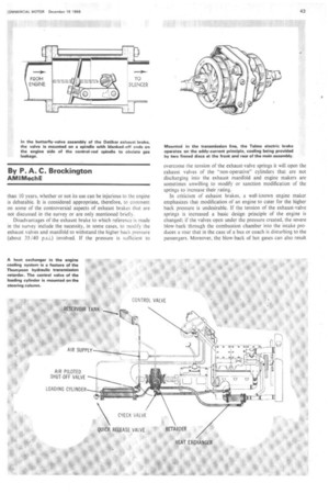
It is observed that the principle of the Thompson retarder is similar to that of a stalled fluid coupling torque converter, a rotor of semi-toroidal cross-section being employed in which a number of vanes is arranged radially and inclined at 45 degrees to the direction of rotation. The vanes of the stator, which is of similar form, are inclined at 45 degrees in the opposite direction.
When fluid is introduced to the unit by an air-pressure-operated loading cylinder, a vortex motion is imparted to the fluid, the temperature of which increases in proportion to the work performed in varying its velocity. The rotor also acts as a centrifugal pump to circulate the fluid through a peripheral port to a heat exchanger and to return the fluid to an inlet port. Incorporated in parallel with the engine cooling, the heat exchanger obviates undue reduction of the engine temperature when the vehicle is continuously retarded on a long downhill gradient. A substantial portion of the heat generated is, however, dissipated to atmosphere by the finned aluminium housing.
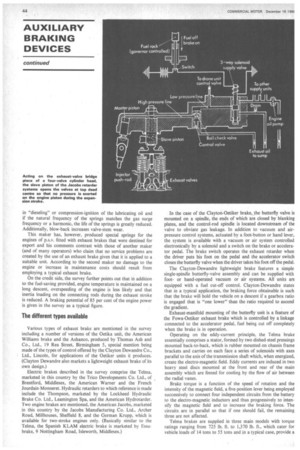
• The Hydrotarder has a maximum power-absorption capacity of 100 h.p. at 935 r.p.m. and at 1,870 r.p.m. its capacity is . increased to 730 h.p., the braking torque being increased at a rate considerably greater than that at which the kinetic energy of the vehicle increases with speed. The heat generated by the turbulent flow is dissipated by circulating the fluid through a heat exchanger in the engine cooling system, the type of retarder fluid employed—oil or water—being determined by the brake operating conditions of the vehicle. To apply the brake, the driver opens a control valve in the inlet line to maintain the required speed.
The Jacobs brake is suitable for fitting to the majority of engines having four-valve cylinder heads and basically comprises a master hydraulic cylinder which operates slave pistons in contact with the bridge pieces of the exhaust valves when fluid is supplied to the circuit from the engine lubricating system by means of a solenoidactuated control valve. The Krupp brake varies the camshaft position (of two-stroke engines), so that the exhaust valves are closed for the full travel of the piston on its upward stroke, control being in the form of a lever on the dashboard.