


A NEW MOUNTING FOR GEARSHAFTS.
Page 68
If you've noticed an error in this article please click here to report it so we can fix it.
A Résumé of Recently Published Patent Specifications.
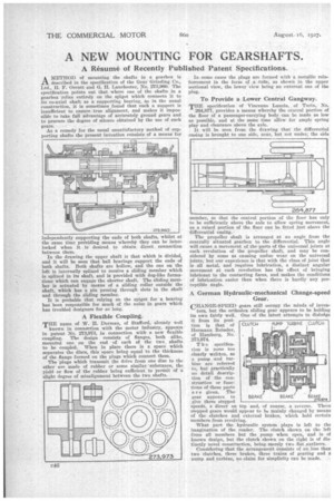
AMETHOD of mounting the shafts in a gearbox is described in the specification of the Gear Grinding Co., Ltd., H. F. Orcutt and G. H. Lanchester, No. 273,960. The specification points out that where one of the shafts in a gearbox relies entirely on the spigot which connects it to its co-axial shaft as a supporting bearing, as in the usual construction, it is sometimes found that such a support is insufficient to ensure true alignment, and makes it impossible to take full advantage of accurately ground gears and to procure the degree of silence obtained by the use of such
gears. .
As a remedy for the usual unsatisfactory method of supporting shafts the present invention consists of a means for independently supporting the ends of both shafts, whilst at the seine time prtividing Means whereby they can be interlocked when it is desired to obtain direct connection between them.
In the drawing the upper shaft is that which is divided, and it will be seen that ball bearings support the ends of both shafts. Both shafts are hollow, and the one on the left is internally splined to receive a sliding member which is splined in its shaft, and is provided with dog-like formations which can engage the shorter shaft. The sliding member is actuated by means of a sliding collar outside the shaft, which has a pin passing through slots in the shaft and through the sliding member.
It is probable that relying on the spigot for a bearing has been responsible for much of the noise in gears which has troubled designers for so long.
A Flexible Coupling.
TEE name of W. B. Dorman' of Stafford, already well
known in connection with the motor industry, appears in patent No. 273,973, in connection with a new flexible coupling. The design consists of flanges, both alike, mounted one on the end of each of the two shafts to be coupled. When in place there is a space which separates the discs, this space being equal to the thickness of the flange formed on the plugs which connect them.
The plugs which transmit the drive from one disc to the other are made of rubber or some similar -substance, the yield or flow of the rubber being sufficient to permit of a slight degree of misalignment between the two shafts.
In some cases the plugs are formed with a metallic reinforcement in the form of is tube, as shown in the upper sectional view, the lower view being an external one of the plug. .
To Provide a Lower Central Gangway.
THE specification of Vincenzo Lancia, of Turin, No. 264,877, provides a means whereby the central portion of the floor of a passenger-carrying body can be made as low as possible, and at the same time allow for ample spring play and clearance above the axle.
It will be seen from the drawing that the differential casing is brought to one side, near, but not under, the side umber, so that the central portion of the floor has only to be sufficiently above the axle to allow spring movement, as a raised portion of the floor can be fitted just above the differential casing.
The propeller shaft is arranged at an angle from the centrally situated gearbox to the differential. This angle will cause a movement of the parts of the universal joints at each revolution of the propeller shaft, and may be considered by some as causing undue wear on the universal joints, but our experience is that with the class of joint that is all metal, and requires lubrication, a distinct angular movement at each revolution has the effect of bringing lubricant to the contacting faces, and makes the conditions of lubrication easier than when there is hardly any perceptible angle.
A German Hydraulic-mechanical Change-speed
CHANGE-SPEED gears still occupy the minds of inven tors, but the orthodox sliding gear appears to be holding its own fairly well. One of the latest attempts to dislodge it from its position is that'of Hermann Reiseler, of Hamburg, No. 273,974.
The specification is none too clearly written, as a pump and turbine are referred to, but practically no detail description of the construction or film; tions of these parts are given. The gear appears to give three stepped speeds, a direct on top and, of course, a reverse. These stepped gears would appear to be mainly changed by means of the clutches and external brakes, which hold certain members from revolving.
What part the hydraulic system plays is left to the imagination of the reader. The clutch shown on the left frees all members but the _pump when open, and is of known design, but the clutch shown on the right is of distinctly novel construction, being,merely two flat surfaces. Considering that the arrangement consists of no less than two clutches, three brakes, three trains of gearing and a Dump and turbine, no claim for simplicity can be made. CLUTCI-4 PUMP
TURBINE CLUTGI-1
BRAKE
.0.4* • t BRAKE 273,974 BRAKE/