


Patents Completed.
Page 26
If you've noticed an error in this article please click here to report it so we can fix it.
APPARATUS FOR 1214:MOVING SNOW FROM ROAD SURFACES.Emerson—No. 15,897, dated 10th July,
1907.—A motor-driven vehicle (a) carries a series of transversely-arranged furnaces (b). A tank, in which the flues are arranged, is placed above the furnaces (b), the flues terminating in a common shaft or chimney (h). The snow is removed from the ground by means of a scoop (m) which is hinged to a chute (p). A chain conveyor (o), within the chute (0), carries the snow from the scoop (m) up into the tank (e) where it is melted. A mud-drum or receptacle is also provided to collect any mud and refuse that may be taken up from the road.
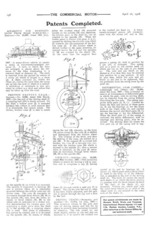
FRICTION DRIVING GEAR.— Gawron.—No. 6,340, dated 15th March, 1907.—On the end of the driving shaft (1) a coupling half (151) is firmly secured, On the shaft a hollow cone (2) is mounted between two collars in such manner that it is adjustable, but cannot rotate. The driven, friction cone (3) is able to rotate on the spindle (4) on which it is mounted. The spindle is supported in hearings (41) and a friction wheel (5) is adjustably mounted between the hollow cone and the driven cone. The cone (3) transmits its movement through bevel wheels (23, 18) to the spindle (16), and, from the latter, by means of 'bevel wheels (35, 36) to the wheel axle (a) indicated by a dotted line. For disconnecting the friction gear, and employing a direct drive from the shaft (1) to the spindle (16), a coupling sleeve (15) is used. This latter is adjustable, but cannot be rotated, and it is mounted on the spindle (16), by means of which,
either the toothed whcel (18) mounted loosely on the spindle (16) and, therefore, the friction gear, or the shaft (1), can be coupled to the spindle (16). When the lowest speed is thrown into gear, it is increased by shifting the friction cone wheel (5) towards the circumference of the hollow cone (2). If the friction wheel is shifted further in the &eine direction, its support moves the rod and the spindles (1, 16) are coupled by the sleeve (15). At the same time the support thus moves the rod (19) whereby, as the lever (19) pivots about 21, the cone (3) is shifted and disengaged from the friction wheel (5). The rotation of the lever, and thus the shifting of the cone, are limited by a pin (20). If the support (6) is moved still further, the cone (3) is brought into contact with the friction cone (24) which is secured to the spindle (1) ; thus a reverse drive is obtained, as the cone (3) transmits its movement through bevel wheels (23, 18) to the spindle (16).
LOCK-NUT.—Schlislen—No. 24,038, dated 30th October, 1907.—This invention relates to means for locking a mit in position and it comprises a cap (3) having holes (5) through which a split pin (7) is passed. The cap fits over the nut (1), after it has been finally adjusted, and the split pin is passed through the cap and a hole in the bolt.
DRIVING CHAINS.—Brampton and Another.—No. 15,072, 1st July, 1907.— This invention relates to the pins and nuts of driving chains and has for its object to prevent their becoming loosened by vibration. The side plates (a) are made slightly thicker at one end and are recessed at a2 to receive the toothed Out or the toothed pin head (c). A transversely-arranged groove (a3) communicates with the recess (a2) and in this groove a spring (el), held in position by a pin (d1), is arranged. This spring acts as a pawl on the ratchet teeth (ei) which are cut on the nuts or pin heads (c). The nuts and pin heads (c) are slotted at el so that they may be screwed into position by a peg spanner. It will be seen that, whilst the nuts and pin heads (c) are free to be tightened, they are prevented from becoming loose by the pawl (d).
DIFFERENTIAL GEAR CASING.— Lamplough and Others.—No. 13,345, dated 8th June, 1907.—This invention relates to an arrangement of differential gear in which the gear, with its driving shaft, can be removed from the casing without disturbing the live axle. The casing comprises three parts (A, B, C). Carried between the first and second of these parts (A, B) are the bearings (a) for the inner ends of the wheel axles (b), and carried between the second and third parts (B, C) are the bearings (c) for the differential. When the third part (C) of the casing is removed, the entire differential, with its bearings and driving parts, may be removed. The driving shaft (d) enters the first part (A) of the casing and is sup ported at its end by bearings (e) . A pinion (f), which gears with a bevel wheel (g) fixed to the body (h) of the differential, is attached to the end of the driving shaft (d). The body (h) carries the usual stub shafts (i) 00 which the bevel pinions (j), gearing with the bevel wheels (k) fixed on the ends of the shafts (I), are mounted. Pinions (m), which gear with the usual bevel wheels (a) on each of the wheel axles (b), are secured to the outer ends of the shafts (I).