


DETAIL DESIGN OF MOTOR PLOUGHS.
Page 22
If you've noticed an error in this article please click here to report it so we can fix it.
A Résumé of Recently Published Patent Specifications
If numbers be anything to go by, the self-contained combined motor and plough is likely to have a considerable vogue in this country, and there are two patents this week by prominent makers of this type of machine. No. 124,660 is by W. E. Martin, of Stamford, and is an arrangement whereby the plough is raised and.lowerecl by engine power. _
A grooved friction pinioreavheel is mounted on the clutch shafi,, and 'a larger one on a universally-jointed shaft. which runs to the rear of the machine is capable of being :moved into or out of engagement with the pinion. At its rear end this articulated shaft carries a worm which engages with a wheel on a cranked shaft. The latter is coupled by a simple saddle arrangement, which permits of lateral movement, to the rear end of the plough frame. Upon engagement.of the friction wheels, this gear revolves the cranked shaft, and either lifts or lowers the rear end of the plough according to the position of the crank. As the shaft revolves always in the same direction it is necessary to provide for its coming to rest m either the upper or lewer of the two extreme positions. This is effected by means of a trip gear which disengages the friction pulleys and eimultaneously applies a brake to the driven one when the-crank reaches either of those two important. points in its movement. Coupling rods communicate between this same cranked shaft and a bellcrank lever nearer flip front end of the machine, and another rod couples this lever to the front end of. the plough frame, so that. lifting or lowering of the whole implement is carried out simultaneously.
The gearing is thrown into operation by means of a hand lever, and provision 'c50 is also made 'for it to be operated through the medians of a pedal. It is thus possible for the driver to manipulate the ploughs either whilst walking by the,siaeaof the machine by means of the hand lever, or when sitting upon it ; he then uses the pedal. The usual mechanism for altering the width and depth of the furrow is, of eouree, included.
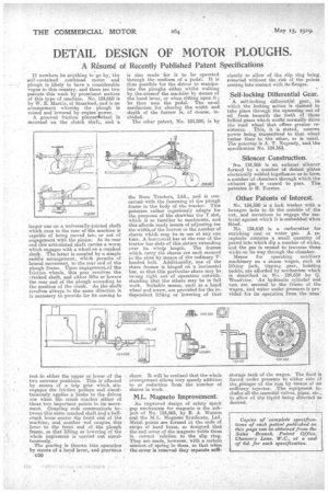
The other patent, No. 124,590, is by
the Boon Tractors, Ltd., and is concerned with the fastening of the plough frame to the body of the tractor. This patentee rather ingeniously adapts for the purposes of the drawbar the T slot, which is so familiar to machinists, and this affords ready means of adjusting tor the width.of the furrow or the number of shares which may be in use at any one, time. A horizontal bar at the rear of the tractor has slots of this nature extending over its whole length. The frames which carry the shares are each secured in the slots by means of the ordinary Theaded bolt. Additionally, one of the share frames is hinged on a horizontal bar, so that this particular share may be swung right out of operation notwithstanding that the others may be in full work. Suitable means, such as a hand wheel and screw, are provided for the in-dependent lifting or lowering of that
share. It will be realized that the whole arrangement allows very speedy addition to or reduction irom the 'number of shares in work.
M.L. Magneto Improvement..
An improved design of safety spark gap mechanism for magneto is the subject of No. 124,665, by E. A Watson and the M.L. Magneto Syndicate; Ltd. Metal points are formed at the ends of strips of hard brass, so designed that the end cover of the magneto holds them in correct relation to the slip ring. They are made, however, with a certain amount of spring in them, so that when the cover is removed they separate auffi
eiontly to allow of the slip ring being removed without the risk of the points coming into contact with its flanges.
Self-locking Differential Gear.
A self-locking differential gear, in which the lacking action is claimed to take place through the squeezing out of oil from beneath the teeth of those helical gears which would normally drive the road wheel that offers greater re sistance. This, it is stated, ensures power being transmitted to that wheel rather than to the other, as ie The patentee is A. T. Nogrady, and the specification No. 124,563..
Silencer Construction.
No. 124,556 is an exhaust silencer lermed by a number of dished plates electrically welded together-so asto form. a number of chambers through which the exhaust gas is caused to pass. The patentee is II. Forster. •
Other Patents of Interest.
No. 124,596is a lock washer with a hexagon hole to fit the outside of the nut, and serrations to engage the material against which it is embedded when fitted.
No. 124,610 is a carburetter for enriching coal or water gas. A receptacle contains a small quantity of petrol into which dip a number of wicks, and the as is caused to traverse those wicks on its way through the chamber.
Means for operating auxiliary machinery on a steam -wagon, such as lifting jack, tipping gear, hoisting tackle, are afforded by mechanism which is described in No. 124,634 by G. Woodvine. -An hydraulic cylinder and ram are secured to the frame of the wagon, and water under pressure is pro vided for its operation from the usua
storage tank of the wagon. The fluid is forced under pressure to either side of the „plunger of the ram by means of an ordinary injector. The equipment includes all the essential valves, pipes, etc., to allow of the liquid being directed-as desired.