


Know Your Air Brakes
Page 48
If you've noticed an error in this article please click here to report it so we can fix it.
si Part 17—Air-actuating Cylinder for -2 Hydraulic Systems WITHWincreasing demands for more increasing power, greater use is being made of air pressure to boost existing hydraulic brake systems. The type of actuating cylinder used is much the same as the standard brake chamber, other than its mounting bracket which is designed to accept one or more types of hydraulic master cylinder, and acts as an adapter to convert the two-bolt fixing of the air chamber to the three-bolt fixing of the hydraulic cylinder.
One of the earlier problems with airboosted hydraulic combinations was the question of determining the amount of travel of the hydraulic plunger, and setting up was often rather "hit and miss". However, on the Clayton-Dewandre air chamber this problem is neatly taken care of by an indicator rod.
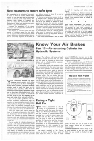
This rod comes into contact with the head of the push-rod assembly, sited inside the diaphragm. On the larger cylinders it passes out through the hollow, upper airchamber stud, and is held in the maximum stroke position by a friction washer in the end of the nut.
On the smaller air cylinders, it passes out through a hole in the air chamber end, where again it is held by a friction 0-ring, this time in a recess between the cylinder end and the bracket and located by shims. These shims must always be replaced, as they determine and maintain the correct clearance between the air-cylinder push rod and hydraulic plunger. The indicator rod has a red mark inscribed towards its free end, and when this red mark is showing up clear of the hollow bolt or cylinder end, the brakes are in need of adjustment.
As mentioned earlier, this actuating cylinder is constructed in the same way as the normal brake cylinder. At the bracket end is the non-pressure cover, inside of which is the seal and seal spring, followed by the main return spring, the push rod, diaphragm and pressure cover. The two covers with the diaphragm between form a sandwich which is gripped by the clamping ring. In turn this ring is closed firmly on all three together by special spfined head bolts and extension nuts.
On fitting the clamping ring over the three parts, difficulty can be met in closing the clamp enough to fit the first bolt and nut. This is overcome by inserting one side of the clamp gap in the vice, or using a pair of mole grips. Servicing follows the same pattern as the normal brake chamber. Dismantle at around 50,000-mile intervals, and at this time it is wise to renew the diaphragm or fit a factory exchange unit.
To test a cylinder in use, seal off three of the four breather holes in the non-pressure cover and apply soap and water to the fourth hole (these holes are sited around the cover near the flange). Then apply the brake, and at any sign of bubbles renew the diaphragm.