


Transmission Unit for Petrolelectric Vehicle
Page 38
If you've noticed an error in this article please click here to report it so we can fix it.
PETROL-ELECTR1C vehicles were once quite a common type, but were handicapped in competing with
types partly because of the obvious disadvantages attached to the incorporation of both a generator and a motor. A new design, in which the duties of these two unit's are performed by one, is disclosed in patent No. .537,647, by Li. Franco, Junior, Ill, Breightrnet Drive, Bolton; J. Franco, Senior, 18, Sheringham Drive, Swinton, and G. ifarlow, 29, Dorset Avenue, Moss Side, Manchester.
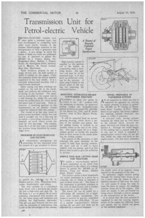
These• inventors propose to use a single electric unit, the field system of which is rotated by the engine, whilst' the armature forms the driven member connected to the road wheels. It is a four-pole series-wound machine, with a wave-wound armature.
Outer casing and field windings are carried on the end (2) of the crank'shaft, and perform the additional duty of acting as the flywheel. The armature is journailed at the engine end in a ball bearing (1), whilst the rear end forms the cardan.shaft (3), which drives the usual type of back axle. There is, however, a reversing gearbox in the transmission, as an electric reverse cannot-be obtained with this system.
• The circuit is of the type usual in series-wound machines, except that one lead is brought out via a slip-ring (4) to enable a controlling resistance to be • inserted; an earth return avoids the need for two slip-rings. The commutator (5) is of the face type, to prevent the brushes being disturbed by centrifugal force.
PROGRESS IN ELECTROSTATIC GAS FILTERS
AN electrostatic precipitator for extracting the fine iinpuriLies from the output of a gas producer is shown
a patent No. 537.64. by W. C. Holmes and Co., Ltd., Whitestone Ironworks, Huddersfield, and others.
The, unit consists of a cylindrical body fitted with a low-level, gas intake (2) and a high-level exit pipe (3). In the body is a set of plates (4) at earth potential, interleaved with another set (I), the latter being well insulated and forming the high-tension electrodes. The gas can pass between the two sets with the minimum of obstruction; this is one of the advantages of the scheme. Iiigh-tension current is supplied by the ignition coil of the vehicle, in .conjunction with a rectifying device. The igni, tion coil may be of the standard type, or it may have an additional winding for the purpose. A drain plug is fitted at the lowest point of the casing for removing the extracted matter.
REDUCING HYDRAULIC-BRAKE CUP-WASHER FRICTION rLAIMED to allow the piston to return to the " off" position with the minimum of friction, an improved sealing washer for hydradlic-brake pistons is shown in patenti‘lo. 537,646, by the Rover Co., Ltd., and P. ScottIversen, both of New Meteor Works, Coventry,
It will be observed from an accompanying drawing, which .shows a section of the cylinder and piston, that the sealing washer is located in an annular recess at the end of the cylinder. The upper space Cl) is a longitudinal groove to enable the pressure fluid to have access to the recess housing the sealing washer.
The essence of tte invention is that although the outer diameter of the washer is held from moving endwise, the inner wall (2) is able to move slightly with the piston, and it is this feature that is said to give the reduction in friction, SIMPLE TOOL-BAR LIFTING GEAR FOR TRACTORS iTenable a tractor-hauled agriculural implement to be lifted clear of the ground is the object of a scheme shown in patent No. 537570 by K. Hudson, Lang Lea Works, Halifax Road, Elland, Yorks.
The tractor carries a fixed framework (1) which terminates in a pivot for a cross-bar (5) to which is attached a pair of short levers (4). The frame of the implement is pivotally attached to the ends of these levers., and is further supported by a pair of links (2).
The levers (4) can be raised by a cable-drum (6) operated by a handlever with ratchet mechanism. The frame is lowered by gravity, controlled by a brake on the cable-drum. To act as a partial 'counterbalance, tension springs (3) are used), and these can be adjusted -by a screwed tesisioner.
NOVEL PRINCIPLE IN VAPORIZER SYSTEM
AN oil vaporizer in which the -fuel is regulated for quantity by varying its supply pressure is shown in patent No. 537,687, by W. Challis, 5, Woodsome Road, London, N.W.5, When fitted to an engine, the device replaces the existing, exhaust manifold, the . duties of which it performs.
A east-iron body, having exhaust branches (2) which line up with those in the cylinder block, receives the , gases, the final exit being the pipe connection 4. ,Through the whole length of the casting runs a central tube (3), to one end of which is attached a spring-loaded control valve (1) for the fuel, whilst the other end leads_ to the engine intake. The fuel valve resembles •
the needle valve of an injector, being opened by the pressure of the fuel. .
In operation, engine suction acting through the central tube draws,in air via a small hole (5), mixes it with a metered amount of fuel from the valve (1), and passes it along the tube to meet the main air supply, the resulting mixture being fed to the engine. The main air -supply is also pre-heated by being drawn through a cast-in passage in the exhaust-box of the device.
It is stated that the fuel pressure is regulated to suit the varying requirements of the engine for different loads and speeds, but no details are given of the niethod. employed.