


THE GAS TRACTION EXHIBITION.
Page 8
Page 9
Page 10
Page 11
If you've noticed an error in this article please click here to report it so we can fix it.
Employment of Gas Under Pressure. A New Non-rigid Cylinder and a Well-devised Bus Installation.
At King's College, Strand, London, W.C., there was opened on Monday last an exhibition promoted by the • British Science Guild, with the assent of the Ministry of Munitions, and with the approval of the Board of Trade, and devoted to (1) Products imported chiefly from enemy countries before the war but now manufactured in this country. (2) Products in the manufacture of which we excelled in this country even before the war and exported to enemy countries. (3) Products in the manufacture of which considerable developments have taken place since the war.
The Gas Traction Committee were invited to form a section devoted to the development in which it is interested, and although the space which could be allotted to the section is small (being only the professors' robing room) it is, in a measure, representative, for it comprises the various applications of gas to traction purposes, the appliances, either full size or in model form, and specimens of materials employed. There 3s, as it were, an "annexe" to the section in that the London General Omnibus Co.'s exhibit is shown in the entrance hall, and it will no doubtipuzzle the
thinking person to know how a complete motor omnibus chassis with engine and transmission, driver's cab and gas installation has been got into its position with no apparent means of ingress, for the doorways are certainly not wide enough to pass a bus. The explanation is to be found in the fact that the engineering department of the Omnibus Co. is enterprising, and is not disposed to be beaten by an apparent difficulty. So a chassis has been assembled in the entrance hall from its _component parts, and the result is very etriking,• for it has been polished, painted and varnished and looks quite Olympia-like. The section comprises the following '
exhibits:—
London General Omnibus Co.—Chassis equipped with gas-fuel installation. Stelastic Tyres, Ltd.—The Stelastic B28 gas container and specimens .of wire weaving. Binge! and Co.—The Fiugel gas carburetter and Flugel reducing valve and control. A fitted chassis was also prepared but could not be accommodated. British Automobile Traction Co., Ltd. —Model of composite container. British Rubber Manufactures Ltd.— Model of container and tray arid specimens of material.
Ernest; Lyon Gas Equipment Co., Ltd. —Model of container and tray ; gas carburetter, special charging cock and cutout; Murphy-Lyon carburetter and reducing valve, The Rotary Meter Co., Ltd.—Gas meter.
W. Parkinson and Co.'Gas meter and filler (hand-operated). The Secretary of the Gas Traction Committee has lent a White and Poppe gas carburetter.
The United Automobile Services, Ltd., were to show their patent automatic cutoff valve, but this had not been staged when the exhibition opened. The walls of the robing room have been decorated by a set of framed photographs illustrating the early stages of the development of the gas traction movement.
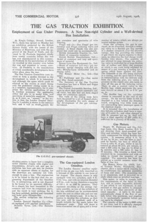
The Gas-equipped London Oninibus.
The London General omnibus equipped to run on gas was fully described as. a forecast of this exhibit in our issue of 1st August. The chassis shown is only equipped with two cylinders, each 4 ft. 6 ins, long, and with an internal diameter of 8 ins., each having therefore a capacity of 110 c. ft. at 1000 lb. pressure. They represent two-fifths of the storage capacity possible, as two of the cylinders of the size exhibited can be accommodated under the seat on either side and one can go tinder the driver's seat. It is the intention to develop the cylinders, so that two only will be required, each of a length suitable for the space below the
passengers' seats. This will mean a more economical use of space and a fewer
number of joints—which are always potential leakage points.
From the cylinders the gas is conveyed, as we described, through a reducing valve to a flexible gas bag carried in a shallow receptacle over the driver's canopy, this bag providing the volume of gas which the engine requires to draw upon, as otherwise the fuel charge would become wire drawn. The quantity of gas allowed to pass through the reducing valve is controlled by a large flexible disc of rubber and fibre, the pressure at which it can work being adjusted by means of a nut forming a seating for a spring which bears against the disc. The underside of the disc being enclosed in a casting, and the space below it being in communication with the delivery pipe from the reducing pipe, any excess of pressure on the supply pipe side tends to shut off the gas at the reducing valve. There is also a control valve in the flexible bag, which maintains the pros-. sure therein at about 2 lb. or 3 lb. per sq. in.
The flexible bag on the exhibited chassis is concealed in the roof of the canopy. On the service buses hi will be disposed in a box behind the direction board, occupying very little room and not encroaching upon passenger space in the slightest degree.
It is intended that the installation of two full-size cylinders shall have a capecity of 9 cubic ft., and when charged to 1000 lb. pressure per sq. in. they will have a total capacity of 600 cubic ft., sufficient for a journey of 20 miles.
Gas Meters.
Messrs. W. Parkinson and Co,. Cottage Lane, City Road, London E.C. 1, are showing their hand-operated gas filler and recorder, which has been specially constructed for filling flexible con tainers, It measures about 4 ft. by 18 ins. by 18 ins., and the filler is operated by handle, one turn of which delivers a cubic ft. of gas, whilst it can be 'rotated at about 60 revs, per minute, so that a 250 cubic ft. bag can be filled in 44 minutes and a 600 cubic ft. bag in 10 minutes. The recorder is fitted with standard 21 in. connections and with an index to record the quantity of gas supplied. The apparatus has been approved as a correct measure under the Sales of Gas Act.
The Rotary Meter Co. (1905), Ltd., of Victoria -Works, Whitefiekls, Manchester, show a meter which requires for its construction the minimum quantities of brass and steel. The measuring fan is of aluminium, and is mounted on a shaft which runs on jewelled bearings.
This meter, in order to comply with the reiquirements of the Sales of Gas Act, and to render impossible delivery of 'gas which is not registered,, is constructed so that gas cermet be obtained at a lower rate than one-tenth of the rated capacity. A valve in the meter automatically closes if the flow of gas falls below this minimum, and requires to be mechanically operated before gas can again be obtained.
The capacity of the meter is 6000 cubic ft. per hour, and it is officially stamped as a correct measure under the Act.
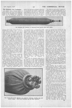
The Stelastic Gas Container.
An exhibit which, without doubt, is really notable and which will Create continued interest throughout the exhibition period is the Stelastic .Gas Container made under the Torkington patents, by telastic Tyres, Ltd., of 76, York Street, Westminster London, S.W. It is a happy coincidence that the name given some years ago to a motor tyre, to-day xactly fits the most advanced idea yet evolVed in gas cylinders, for the conI,aer to which the name is given is made of tel and is sufficiently flexible and locally deformable to entitle it tO the description " elastic." We have been permitted to watch the development of this cylinder almost from the inception of the idea, have been informed ot the problems of design, manufacture and commercializing as they arose one by one, and have been witnesses to the success with which each problem in turn has been solved. And it seems to us that the system of manufacture and the many excellent features of the design should • bring the Stelastic gas container within a measurable distance of being capable of earning the award offered by the Automobile Association.
In our last issue we gave a brief description of materials of • which the container is made. Succinctly put, the container is a rubber receptacle shaped to fit exactly in an outer casing of a fabric composed of interlaced spirals.
Hard drawn steel wire having a tensile strength of 120 tons to the square inch, and tinned to prevent rust, is passed through a machine tool which by 'means of rollers, a die, and central spindle turns it out in a spiral of absolutely, correct pitch. When the required length of
spiral wire has been extruded to the wire is cut and the next length of spiral wire is interlaced in the first as it lies on the table beside the machine tool. The' third length is woven into the second, and so on until what one might term a" sheet"
of interlaced fabric is produced of sufficient size to make the outer casing required. The operation so far is wonderfully rapid and absolutely accurate, and no doubt at the exhibition specimen portions of the fabric may be handled and the spectator will, (himself, he able to thread spirals off and on and will then see how perfectly they mesh.
The sheet of fabric is now formed into a cylinder by the last two spirals being brought , together as a butt joint; by means of another spiral they are joined together so that there is in reality no "
joint" in the common acceptance of the term, and thus a cause of frequent trouble is entirely avoided. The difficulties so, far lay in getting a weaving which should be as strong laterally as it was longitudinally, and after numerous trials and experiments this end was attained, and all internal -pressures up to say, 2000 lb. to the Square inch provided for. At or over that pressure the inventor thinks it may be necessary to use a reinforcing lining of a different weaving that shall resist any tendency to lengthen.
Now with all cylinders which are to he subjected to high internal pressures, the real crux of the design is generally the formation of the ends. In the case of the Stelastic outer casing the problem has been solved in a masterly way, for not only are the ends made perfectly secure, but it is the work of a few minutes only to diamantle the ends. The fabric at each end is " gathered " together in a careful manner and over it is slipped a forged steel ring electrically welded. Then into the gatherings beyrind the ring are driven six conical lead wedges about 3 ins. long. These form an enlarged end beyond the ring and with the ring form an end to the cylinder which will stand the maximum internal pressure which the cylinder is calculated to resist. One end of the outer casing is closed up in this manner and there is then inserted from the other end the rubber bag which is made on the lines of the inner tube of a pneumatic tyre, namely, of the best quality thin rubber. (Strangely enough, experiments have shown that thick rubber is rather a disadvantage than otherwiSe.) This is fitted with a gas pipe at one end and is suitably reinforced with piles of cotton fabric round the pipe seating. The hag being placed endwise in the outer easing, the end of the fabric is gathered together round the pipe, a steel ring is slipped over and lead wedges are driven in exactly as was done in the case of the other end. The container is now complete except for a stop cock.
The weight of a cylinder 4 ft. long by 8 ins, internal diameter, with its rubber hag and pipe, is 27 lb. It would have a capacity of 1.39 pubic ft. At 20 atm°. silieres .(500 lb.) it would contain 27.8 cubic ft. of free gas; at 40=atmospherea 55.6 cubic ft., and at 70 atmospheres (1000 lb.) it would hold 97.3 cubic ft. A cylinder 5 ft. long by 10 ins, diameter would hold at 20 atmospheres 54.5 cubic ft. and at 70 atmospheres 190.75 cable ft. of free gas. • The cylinders can be made of any length 'up•to, say, 10 ft. or 12 ft., and of any reasonable diameter. Tests under hydraulic pressure have been made up to 650 lb. per square in. .
It is common knowledge that virtually
all accidents with steel cylinders have occurred through dropping, the metal fracturing under the shock: -Hence the objection that may reasonably be made to avoidable handling or moving of charged cylinders. But the Stelastic gas container cannot labour under this disability, for the fabric being capable of local distortion and the cylinder being sufficiently flexible and being constructed as described there can be no possibility of fracture.
In the event, • however, of a defeet
arising in the rubber bag, the pipe—or its seating, or even in the event of damage to any part of the outer casing, it will be at once apparent that the whole apparatus can he dismantled, the defective hag be replaced and even a new section of spiral wires can be inserted if required. A cylinder has been thus dismantled and provided with a new bag
and reassembled within 20 minutes. .
• We can also see another advantage
from this method of construction. By removing or adding spiral wires and changing the rings (and of course the bag) the cylinders can be altered -in
diameter should it be desired to make changes in an installation.
The question of cost has not yet been entirely settled, but as compared with other methods of construction the Stela.stie method is cheap. In fact the rubber bag is the most expensive part.
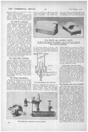
The B.R.M. Container.
The flexible gas container made lev'the British Rubber Manufactures, Ltd., Agnes Works, Agnes Road, Acton, London, W. 3, is exemplified in a 'model showing a tray and container,, the method of securing the latter to the former being very Clearly seen. In fact, • we clemnwnd exceedingly the idea of using models adopted at this exhibition, as the average gas container fitted to a vehicle is too big and too, greatly elevated for the details of construction to be open to examination. In.' the model it can be seen that the container is provided on each of its four sides with a deep and well-secured flap, the lower end of which is secured to the tray by an outside fillet Samples of the Materials employed are shown, the fabrics hieing constructed to the specification of the Gas Traction Committee. The samples show : (1) Egyptian cotton in a raw state; 2i the material treated with five coats of rubber; (3) the finished material put together with an inner curface of 12 coats of Para rubber, and with the outside separately coated.
The Semi-rigid Container.
A good example of the semi-rigid container is rhown in model form by the British Automobile Traction Co., Ltd., Manchester Hotel, Aldersgitte 'Street, E.C., having been constructed in the shops of the East Kent Road Car Co., Ltd., Canterbury. The lower box portion is made of boards lined with fabric to render it gastight; the collapsible portion, which is made of fabric complying with the specification of the Gas Traction Committee, has a capacity approximately the same as that of the rigid portion.
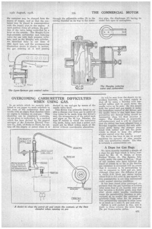
The Flugel Installation.
Considerable enterprise has been shown by Messrs. B. flugel and Co., of 33a, Green Lanes, London, N. 16, in the design of fittings and equipment snitable for the supply and control of gas carried in cylinders under high pressure. They have not specialized on cylinders, but are prepared to employ the most efficient gas containers that will prcvidc them with what is tequired—a sufficient quantity of free gas carried in the smallest and lightest receptacles. The vehicle fitted up with their system is shown in the courtyard, space not being available in the building. In the Robing Room there are shown the Flugel gas carburetter
which we described and illustrated in Our issue of Ilth August, and the combined reducing valve and expansion chamber which, carried on the dashboard,effects a reduction of pressure
from, toy, 120 atmoepheies dawn to the atmosphere working in conjunction with an adjustable valve which serves to effect
further reduction of pressure as may be required. The horizontal reservoir below the reducing valve receives the gas at about atmospheric pressure, and thus provides a volume of gas for the engine to draw upon. The gas can be shut off at two points, and a reservoir full of gas is always available at the correct pres sure for restarting the engine. Specimen steel cylinders are also shown. This equipment has been approved by the Gas Traction Committee in respect of the use on a commeecial scale of 20 goodecarrying vehicles in London.
Automatic Cut-off Valve.
The Jolly automatic cut-off gas filling valve is introduced into the system on the charging side, the lifting of the gasbag acting through a cord on a restraining lever or trigger which normally holds the butterfly valve open. A certain pressure having fully distended the bag the pull on the cord lifts the trigger, and the valve is closed by the action Of a spring as soon as the bag is filled. The valve was expected to be placed on exhibition daring the week. It is a simple and effective device.
The Murphy and Lyon Exhibits
The Ernest Lyon Gas Equipment Co., Ltd., of 91, New Bond Street, London, W. 1, also show a model of flexible container and tray constructed on the LyonSpencer system, with its controlling hinged battens and restraining cords. Specimens of fabric are exhibited, and these bear close examination, for there is no concern with a greater knowledge than the Spencers of what is required in the constrnction of a flexible receptacle for coal-gas, their long experience in balloon manufacture having been of incalculable value in this connection. The Lyon-Spencer gas carburetter has e 1-7ein. gas pipe to bring the gas to a central gas jet, which can be regulated in size by means of a conical plug mounted at'the end of a screwed stem. By means of this the throat of the gas inlet can be enlarged or reduced white the engine is running, so as to secure the greatest efficiency. The air intake is capable of minute adjustment froth the outside, and a commendable feature is a screen between the gas duet and the threat to prevent back-firing into the source of supply. The charging cock and cut-out is a tapered rotary valve in a suitable barrel with ports in the valve, so that the container may be charged from the source of supply, and so that the container may be placed in communication with the supply pipe to the engine. A :hird position closes all orifices, the position of the valve being controlled by, a lever on the outside. The Murphy-Lyon high-pressure carburetter and 'reducing valve for use with high pressure cylinders, such as the Murphy safe Cylinder, we described fully in our issue of 18th April last, and the accompanying illustration shows it clearly in section, the gas entering at A and passing
through the adjustable orifice (B) to the mixing chamber on its Way to the indue tion'pipe, the diaphragm (C) having its under face open to atmosphere.