


AN ELECTRIC AUTOMOTIVE TRAILER.
Page 30
If you've noticed an error in this article please click here to report it so we can fix it.
A Resume of Recently Published Patents.
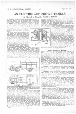
ELD-21'RM Automotive Trailer is the name gi cc by G. D. Peters and Co., Ltd., to the novel tYpe of commercial motor vehicle which they, in cempany with A. L. Brockman, have invented, and which is described in patent specification No. 209,926. It would appear to be, in one sense, a development, of the tractor-trailer combination vehicle, a development along the lines of simplification, for the forward portion of the tractor part of such a combination is eliminated, leaving only the hind—and driving—axle, located' as usual, underneath the pivoted connection for the usual two-wheeled trailer.
A feature Lthis novel vehicle is that it is designed for use as a trailer only, being fitted with a special drawbar attachraent which, when brought into service, automatically disconnects both the driving mechanism and steering gear of The " Automotive Trailer," leaving it free to follow in the wake of the external tractor, as would any ordinary trailer.
The tractor part of the vehicle embodies a simple rectangular frame, to the forward underside section of which is pivoted an underframe, -which closely resembles, both sofas as-its appearance and functionkg are concerned, the perch bars of a chassis of the type in which the rear axle is driven, by double reduction gears of which the final pairs are located in the rear wheels. To this underfrarne the live axle is shackled by longitudinal bars, carried in brackets on the frame. Coil springs at the extreme rear end of the uriderfranie support the main. frame. The lastnamed in the construction described in the specifiCation, supports, at the off side, the electric motor which provides the propulsive power, and at the new side the driver's plat form and thecontrols. The former is arranged in some fashion
closely allied to that "customary on industrial electric trucks, in that, when the man steps from it, the brakes are automatically applied and the control severed. The steering gear is an important feature of the design of this machine. Cross-members on the main frame of the tractor carry a casing which supports, on its upper surface, the lower race of a substantial ball-thrust bearing. A similar casing, carried also by cross-members, which are supported from the forwardly projecting frame of the trailer, carries the 'upper race, and the necessary halls, intervening, support the • weight of the front end of the trailer, with, of course, its load. In the centre of these casings and the ball bearings is a substantial hollow pivot, to the lower end of which is keyed a worm wheel, and this carries at its upper end, on feather keys, the sliding member of a dog clutch. This clutch is controlled by a sod which fits inside the hollow pivot and projects beyond it at its lower end. With the rod in the Tower position, the clutch is disengaged', and, consequently, n30
rotation of the pivot bY means of the worm wheel, which :is Connected to the steering wheel, has no effect. In this position the pivotal connection between tractor and truck differs in no Way from that between the turntable of any ordinary truck and the rest of the vehicle, and with the goers so set the machine is ready for use -as a trailer. . That, however, is not the normal position. A lever below the pivot, with a projection designed to engage the protruding end of 'the rod which controls the above. mentioned clutch, is coupled to a lever on a cross-shaft at the front end of the vehicle on which the drawbar hangs. When the drawbar is not in uses the clutch in question is caused to engage, and the movement of the complete vehicle is then subject to the control of the steering gear. Lifting the drawbar, in order to hitehsup to some other tractor, has the effect of disengaging this steering clutch, as well as another in the power transmission gear:
Several constructions have reference in the patent specifiea Lion, and the design is not confined, in its application, to electrically driven machines. The trailer, •as shown, is fitted with a tipping body, and the simple form of tipping gear is described in detail, in the patent specification.
Other Patents of Interest.
NEA.T and novel is the arrangement of stub axle which is
disclosed in specification No. 210,028, by the Albion Motor Car Co., Ltd., and J. Watt. The stub axle is hollow, and the wheel is mounted on a spindle which revolves inside the axle.The spindle, at its inner end, is supported in a ball bearing which lies inside the stub aide. At its 'outer end, next the wheel, the spindle revolves in a clearance hole, and is actually supported by a ball bearing mounted Oil the outside of the hollow stub axle, and engaging a projecting circumferential flange on the hub of the wheel. The advantage of this construction is that it allows the stub axle to be considerably reduced in diameter, and affords roomfor increased length of pivot bearing, ANOTHER example of Sunbeam servo brake construction is disclosed in specification No. 211,629. It is claimed: that it can be applied to existing vehicles with but slight.
alteration.
AFURTHER brake invention is described in specification 'No. 212,105, by H. S. Dyke. It aims at simplifying the adjustment for wear, and actually provides for such adjust-, ment to be effected while the vehicle is in motion.
PATENT specification No. 212,141 also refers to brakes, and stands to the credit of Bentley Motors, Ltd., and F. T: Burgess. Radial ribs, formed in one with the anchor plate, are so arranged that the brake anchor pin, instead of being overhung, is centrally supported by the rib; the brake shoe being forked at the end, to embrace the rib and take hold of both sides of the pin. The result may he reduced weight for a given strength, or increased strength for the same weight, according to circumstances.
OUTSTANDING amongst the objects of especial interest at the last Commercial Vehicle Rithibition at Olympia were the wheels fitted to the Crossley W.D. subsidy chassis: Cast in aluminiurn, they were handsome, and looked strong, whilst being light. In spetification No. 212,189, the design of these wheels is diselosed. In its simplest form a wheel is made iii halves, the junction being a vertical one, through the middle of the rim, dividing the spokes in two. The halves are bolted together and to a steel hub: Stronger wheels are made by building steel discs into them.
IN the wheel patented by If. H. Duke, in specification No. 212,202, the whole wheel is made of cork and rubber, vulcanized together and stiffened by canvas. It is stiffened by a pair of steel discs, one each side, and the tyre is vulcanized direct on lb the cork-rubber case. '