


Coal-dust Engine With Opposed Pistons
Page 36
If you've noticed an error in this article please click here to report it so we can fix it.
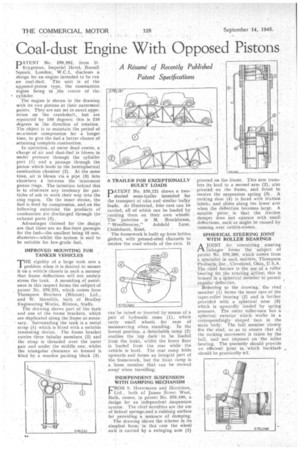
DATENT No. 570,292, from D. / Krygsman, Imperial Hotel, Russell Square, London, W.C.I. discloses a design for an engine•intended to be run on coal-dust, ' The unit is of the opposed-piston type; the combustion region being in the centre of the cylinder.
The engine is shown in the drawing with its two pistons at their outermost . points. They are not set in exact opposition on the crankshaft, but are separated •by 150 degrees; this is 210 degrees in the direction of rotation. The object is to maintain the period of maximum compression for a longer time, to give the fuel a better chance of attaining complete combustion. .
In operation, at outer dead centre, a• charge of air and dust-fuel is blown in under pressure through the cylinder port (1) and a passage through the piston which leads to the hemispherical combustion chamber (2). At the same time, air is blown via a pipe (3) into chambers 4 between the innermost piston rings. The intention behind this is to eliminate any tendency for particles of ash to work their way into the ring region. On the inner stroke, the fuel is fired by .compression, ancl.on the following outstroke the products of combustion are discharged through the exhaust ports (5). • Advantages claimed for the design are that there are no fine-bore.pas&Iges for the fuel—the smallest being 10 mm.. diameter—whilst the system is said to be suitable for low-grade fuel.
IMPROVED MOUNTING FOR TANKER VEHICLES
THE rigidity of a large tank sets a problem when it is desired to mount it on a vehicle chassis in such a manner that frame deflections will not unduly stress the tank. A mounting.of assistance in this respect forms the subject of patent No. 570,221, which comes from Thompson Brothers (Bilston), Ltd., and W. Meredith, both of Bradley Engineering Works, Bilston, Staffs. •
The drawing shows part of the tank and one of the frame brackets, which are duplicated along the frame as necessary. Surrounding the tank is a metal • strap (1) which is fitted with a suitable tensioning device. The frame bracket carries three tubular members (2) and the strap is threaded over the outer pair and under the middle one, whilst the triangular clearance so formed is filled by a wooden packing block (3).
PATENT No. 570,121 shows a two storied semi-trailer intended for the transport of ars and similar bulky lbads. As illtistrated, four ears can be carried, all of which can be loaded by "running them on their own wheels, The patentee is M. Brockhouse,
" Woodbourne," Ashfield Lane, Chislehurst, Kent. '
The framework is built up from lattice girders, with pressed-steel channels to reeeive the road-wheels of the cars. It can be raise,. or lo.weted by -means of a .pair of "hydraulic rams (1), which carry small wheels for ease of manceuvring when standing. in the lowest position, a detachable ramp (2) enables the .top deck. to be loaded from the front, whilst the lower floor is loaded from the rear while the vehicle islevel. The rear ramp folds upwards and forms an integral part of the framework, but the front ramp is a loose member that can be stowed away when travelling.
INDEPENDENT SUSPENSION wrrt-i DAMPING MECHANISM FROM S. Horstmann and Horstman, Ltd., both of James Street West, Bath, comes, in patent No.570,190, a design for an independent _Suspension system. The chief novelties are the use of helical springs;and.-a•zUbbirig surface for providing a measure of damping.
The drawing Shows the Scheme in its simplest form: in this case the wheel axle is carried by a swinging arm (I) pivoted on the frame. This arm transfers its load to a second arm (2), also pivoted on the frame, add fitted to receive the suspension spring (3). A rocking shoe (4) is laced with friction fabric,arid slides along the lower arm when the deflection becomes large. A notable point ., is that the friction damper does riot operate with 'small deflections, such as might be caused by running over cobble-stones.
SPHERICAL STEERING JOINT WITH ROLLER BEARINGS
AJOINT , for connecting steering . linkages forms the " subject of patent Ii. 576,298, which comes from a specialist in such matters, Thompson ' Products, Inc., Cleveland, Ohio, U.S.A. The chief feathre is the use of a roller bearing for the rotating action; this is lion sed in a SplieriCal member to permit angular deflect on
Referring to the drawing; the stud member (1) forms the inner race of the taper-roller hearing' (2) and is further provided with a spherical nose (3) which is upwardly loaded by spring pressure. The outer roller-race has a spherical exterior which works in a correspondingly shaped face in the main body. The ball meinber closely fits the stud, so as to ensure that all the rocking Movement is taken by the ball, and not imposed on the roller • bearing. The assembly should provide an efficient joint in 'which backlash should be practically nil.