


Patents Completed.
Page 24
If you've noticed an error in this article please click here to report it so we can fix it.
The Crompton Road Maker.
R. E. 11. Crompton and N. G. Crompton, No 21,999, dated 5th October, 1911.—This specification describes a machine for applying a coating of road metal to an existing foundation in such a way that it is at once rolled down and
cemented to a surface, A mixture of 'road concrete," that is to say any desired road stone mixed with bituminous or chemical binding material, is carried in a hopper in which a positively driven vane wheel is mounted. This wheel forces the mixture down into a trough. where it is compressed and fed under a roller at the rear of the vehicle. In one construction, the bottom of this trough is formed of a number of parallel sections of an endless wire rope, which is driven so as to feed the material along it. A number of rollers may be provided on each side of the trough to compress the mixture as it travels downwards, and a turnbuckle link is provided to hold the trough up against the big road-roller, this giving an adjustment for the thickness of the layer which is being 'laid. The vehicle is preferably mechanically driven, and the "concrete" mixture is steam-heated until it is deposited on the road surface. All the small rollers are connected by chain gearing to the large roller in order that a fixed rate of surface movement of all of them may be maintained.
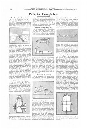
A Cylindrical Valve Gear.
L. S. De Riehelle, No. 681. 1912, dated 3rd October, 1911.—In this valve gear a cylindrical valve chamber is used, set across the top of the cylinder, and communicating with the combustion space. A large number of longitudinal slots are arranged in this cylinder, some of them communicating with the induc
tion pipe from the carburetter, and some with the exhaust pipe, or direct with the atmosphere. Inside this space is the
valve, which consists of a cylinder having similarly arranged longitudinal slots in it,. These are brought to register. as required for working the engine, by a slight rotation of the valve, this being operated by a push-rod and cam, suitably driven from the crankshaft.
A Quick Change Body Van.
R. H. Hopkinson and V. Hopkinson, No. 1095, dated 15th January, 1912.— The body of a motorvan is divided longitudinally in halves, the upper half being made detachable, and so arranged that a separate body may be substituted for it. On the fixed part of the body there are secured cross-bars which are under-cut and extend rearwardly. On the detachable part of the body there are fixed similar cross-bars which are under-cut, and are so positioned that, when the upper part of the body is laid on and pushed forward, these two sets of cross-bars gip one another. To prevent the removable body slipping sideways a dove-tailed joint is made in the cross-bars.
A Motor Road-sweeper.
G. W. Blackburn, No. 27,418, dated 7th December, 1911.—In order to prevent tha sweeping brush being raised
from the ground by vibrations of the rear axle, it is carried on a separate cross-frame with the driving wheels, and the main frame is mounted on this secondary frame by the ordinary elliptical springs. It will be seen that, with this construction, the road brush closely follows the inequalities of the road, but the shocks due to these inequalities are not transmitted to the engine and main framing. One of the side members of this secondary frame is extended out backwards, and is bent round so that it projects sideways beyond the driving wheels and enables the brush to be mounted so as to sweep close to the kerb.
New Chassis Frame Construction.
3. B. Taunton, No. 27,292, dated 5th December, 1911.—In chassis frames which are stamped or pressed from one piece of sheet steel, it has been usual to provide a depression or recess to receive the flywheel and the change-speed gear. According to this invention separate r.xesses are pressed out and formed integral with the frame to constitute the bottom halves of the engine crankcase and gearbcx. A gap is formed between them to accommodate the flywheel and clutch. There may also be provided depressions which receive the crankshaft bearings and keep them in alignment.
Acetylene Generator.
J. M. Jackson, No. 21,836, dated 4th October, 1911.—This generator has been designed with a view to eliminating all soldered joints in the construction, as these are found to be unsatisfactory. A main casing, which is cylindrical in form and open at both ends, has a, partition formed integrally with it which divides it into two portions. This casing is preferably of a single piece of cast metal or it may be made of porcelain or baked clay if desired. The upper compartment is closed by a domed plate in which the needle drip-valve is mounted. The seating for the valve is fixed in the partition and is extended downwards some distance, where it carries a perforated plate which supports the ordinary purifying materials. The water supply is carried in the top chamber and passes through the drip. valve into the bottom chamber which contains the carbide. A thin metal liner is carried on the baseplate and completely encloses the carbide, FO that the latter does not Come in contact with the sides of the main casing. The gas supply is led off by a tube passing through the water reservoir and water seal, so that a safety valve action is thus obtained.