 1
1 2
2 3
3 4
4 5
5 6
6 7
7 8
8 9
9 10
10 11
11 12
12 13
13 14
14 15
15 16
16 17
17 18
18 19
19 20
20 21
21 22
22 23
23 24
24 25
25 26
26 27
27 28
28 29
29 30
30 31
31 32
32 33
33 34
34 35
35 36
36 37
37 38
38 39
39 40
40 41
41 42
42 43
43 44
44 45
45 46
46 47
47 48
48 49
49 50
50 51
51 52
52 53
53 54
54 55
55 56
56 57
57 58
58 59
59 60
60 61
61 62
62 63
63 64
64 65
65 66
66 67
67 68
68 69
69 70
70 71
71 72
72 73
73 74
74 75
75 76
76 77
77 78
78 79
79 80
80 81
81 82
82 83
83 84
84 85
85 86
86 87
87 88
88 89
89 90
90 91
91 92
92 93
93 94
94 95
95 96
96 97
97 98
98 99
99 100
100 101
101 102
102 103
103 104
104 105
105 106
106 107
107 108
108 109
109 110
110 111
111 112
112 113
113 114
114 115
115 116
116 117
117 118
118 119
119 120
120 121
121 122
122 123
123 124
124 125
125 126
126 127
127 128
128 129
129 130
130 131
131 132
132 133
133 134
134 135
135 136
136 137
137 138
138 139
139 140
140 141
141 142
142 143
143 144
144 145
145 146
146 147
147 148
148 149
149 150
150 151
151 152
152 153
153 154
154 155
155 156
156 157
157 158
158 159
159 160
160 161
161 162
162 163
163 164
164 165
165 166
166 167
167 168
168 169
169 170
170 171
171 172
172 Wooden Frame for Sugar Tank Body
Page 110
If you've noticed an error in this article please click here to report it so we can fix it.
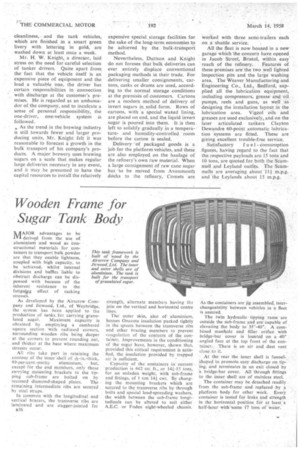
MAJOR advantages to be nri derived from the use of aluminium and wood as constructional materials for containers to transport bulk powder are that they enable lightness, coupled with high capacity, to be -achieved, whilst internal divisions and baffles liable to obstruct discharge can be dispensed with because of the inherent resistance to the fatiguipg effect of racking stresses.
As developed by the Airscrew Company and Jicwood, Ltd., of Weybridge, the system has been applied to the production of tanks, for carrying granu lated sugar. Maximum capacity is obtained by employing a cambered square section with radiused corners, surrounding woodenribs being deeper at the corners to prevent rounding out, and thicker at the base where maximum stresses occur.
All ribs take part in retaining the contour of the inner 'shell of -6;-in.-thick, 99-per-cent.-purity aluminium, but, except for the end members, only those carrying mounting brackets to the tipping sub-frame are bolted on by
recessed diamond-shaped plates. The remaining intermediate ribs are secured by steel straps.
In common with the longitudinal and vertical bracers, the transverse ribs are laminated and are stagger-jointed for
$36 strength, alternate members having the join on the vertical and horizontal centre lines.
The outer skin, also of aluminium. houses Onazote insulation packed tightly in the spaces between the transverse ribs and other bracing members to prevent coaEulation of the contents of the container. Improvements in the conditioning of the sugar have, however, shown that, provided this critical requirement is satisfied, the insulation provided by trapped air is sufficient.
Capacity of the containers in current production is 642 cu. ft., or 14-,3,-I5 tons, for an unladen weight, with sub-frame and fittings, of 1 ton 141 cwt. By changing the mounting brackets which are secured to the transverse ribs by through bolts and special load-spreading washers, the width between the sub-frame longi-tudinals can be altered to suit either A.E.C. or Foden eight-wheeled chassis.
As the containers are jig assembled, interchangeability between vehicles in a fleet is assured.
The twin hydraulic tipping rams are outside the sub-frame and are capable of elevating the body to 35°-40°. A combined manhole and filler °rifled with bridge-bar cover is lotrated On a 40° angled face at the top front of the container.There is an air and dust vent close to it.
At the rear the inner shell is funnelshaped to promote easy discharge on tipbig, and terminates in an exit closed by a bridge-bar cover. All "through fittings to the inner shell are of stainless steel.
The container may be detached readily from the sub-frame and replaced by a platform body for other work. Every container is tested for leaks and strength in the horizontal position for at least a half-hour witlf-some 17 tons of water.