


AN IMPROVED METHOD OF VAPORIZING FUEL.
Page 28
If you've noticed an error in this article please click here to report it so we can fix it.
A Résumé of Recently Published Patent Specifications.
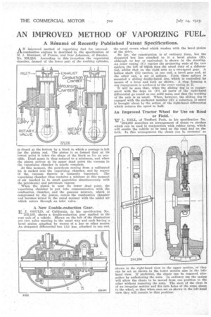
AN improved method of vaporizing fuel for internalcombustion engines is described in the specification of M. J. Montazet, f Prance, and Ivar Johanson, of Sweden, No. 221,216. According to this invention the vaporizing chamber, formed of the lower part of the working cylinder,
is closed at the bottom by a block in which a passage is left for the piston rod. The piston is so formed that at its lowest point it takes the shape of the block so far as possible. Dead space is thus reduced to a minimum, and when the piston arrives at its upper dead point the vacuum in the vaporizing chamber is nearly complete.
At this moment, the petroleum coming from a calibrated jet is sucked into the vaporizing chamber, and by reason of the vacuum therein is instantly vaporized. The vaporizing chamber thus contains a mixture at this moment of air (sucked in in small quantities simultaneously with the petroleum) and petroleum vapour.
When the piston is near its lower dead point, the vaporizing chamber is put into communication with the combustion chamber, and the gaseous mixture, which is compressed by the piston, enters the combustion chamber and becomes mixed in the usual manner with the added air which enters through an inlet valve.
A New Double-reduction Gear.
E S. GOULD, of California. in his specification No.
'235.107, shows a double-reduction gear applied to the rear axle of a vehicle. Shown on the left of the illustration are two axles meeting in the usual way and each having a bevel pinion attached by means of a key or other means. An elongated differential box (A) has, attached to one end, the usual crown wheel which meshes with the bevel pinion of the drive.
So tar, the construction is of ordinary form, but the elongated box has attached to it a bevel pinion (B), although no key or equivalent is shown in the drawing. An inner casing (C) carries the projecting ends of the two spiders, the left of which does the usual duty of a differential, whilst that on the right acts as a two-speed gear. A hollow shaft (D) carries, at one end, a bevel gear and, at the other end, a set of splines. Upon these splines is mounted a sliding double-faced dog, which is controlled by means of a lever and fork as shown. A ring forming a aog engagement is anchored to the outer easing at E.
It will be seen that, when the sliding• dog is in engagement with the dogs on (D) all parts of the right-hand differential go round as one solid mass, and that the working of the axle is as usual. When, however, the sliding dog is engaged with the anchored member (E) a reduction of speed is brought about by the action of the right-hand differential which reduces the speed to half.
An Improved Tractor Wheel for Use on Road or Field.
vtr L. HILL, of Trafford Park, in his specification No.
'2434,260 describes an arrangement of cleats et. strakes which can be used in conjunction with rubber tyres, which will enable the vehicle to be used on the road and on the field. In this arrangement the cleats can be retract ee as shown in the right-hand view in the upper section, or they can be set as shown in the lower section also in the lefthand view. If preferred, the cleats can be removed altogether by unfastening the nuts. In ordinary use the aping will allow the cleats to be moved from one position to the other without removing the nuts. The stem of the cleat is of an irregular section and fits into holes of the same shape in the wheel, so that when once set as shown in the left-hand view they will remain in that position: