


SIMPLE MECHANICS
Page 66
Page 67
If you've noticed an error in this article please click here to report it so we can fix it.
UTCIIES I
A VEHICLE powered by a steam engine has the engine directly coupled to the road wheels and when it starts away from rest steam is admitted into the cylinder and the vehicle moves away.
When an internal combustion engine is fitted to a vehicle, such a simple arrangement is not possible because the engine has to be revolving at considerable speed before it develops sufficient torque to move the vehicle.
A device to connect the revolving engine to the stationary road wheels, through the transmission system, is, therefore, necessary and the clutch fulfils this function. It enables the drive from the engine to the gearbox to be disconnected so that a gear can be engaged and then for the drive to be taken up smoothly and progressively.
Widely used
The most widely used form of clutch is the single plate friction type,, a simplified diagram of which appears in Figure 1. It consists of a centre plate which is clamped between two outer plates. The rear face of the engine flywheel forms one of the
,uter plates and the other is the iressure plate which is mounted lside the clutch cover which, in Jrn, is bolted to the flywheel. he pressure plate is forced awards the flywheel by a umber of coil springs arranged 3dially inside the cover.
Three levers, or fingers, are arried on pivots on the clutch over and these are so arranged iat they can move the pressure late away from the flywheel gainst the pressure of the prings, so freeing the centre late when the driver presses le clutch pedal.
The clutch fingers are moved iwardly by the pressure of a arbon or ball thrust release earing carried on a forked laft. This shaft is connected to le driver's clutch pedal by leans of rods, cables or by a ydraulic system. Figure 2 bows the complete clutch unit olted to the flywheel of an enine.
The hub of the centre plate is Iounted on the splined gearbox lout shaft and is free to move long the splines. The gearbox -left is supported at the front nd by a spigot bearing in the ywheel. The centre plate hub is sually connected to the centre late by a set of radially rranged springs to cushion the
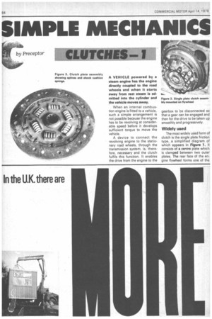
shock when the clutch takes up the drive. These springs are shown on the centre plate in Figure 3.
The plate itself consists of a segmented disc, each segment being slightly offset from its neighbour. This allows the friction discs, which are riveted to the segments, to be slightly apart when not under pressure and gives a more progressive clutch engagement when the linings are squeezed together as the drive is taken up.
The pressure plate is caused to revolve as one with the flywheel projections on it engaging with slots in the clutch cover. Alternatively, tempered steel straps arranged tangentially between the pressure plate and the cover are used. These eliminate all friction between the pressure plate and the cover while their flexibility allows for axial movement of the pressure plate.
Friction material used for clutch linings consists of asbestos and resin bonded together to form the correct shape. Sometimes brass or zinc wire is included to increase the wearing qualities of the linings and assist in the dissipation of the considerable heat generatedwhen the clutch is slipping be
fore the drive is completely taken up.
Common practice
It is now common practice for the clutch to be contained in a bell housing at the rear end of the engine, the flywheel being utilised for one of the "plates" as previously described, and for the gearbox to be bolted directly behind the bell housing or cast in one piece with the bell housing.