


An L.G.O.C.
Page 72
If you've noticed an error in this article please click here to report it so we can fix it.
Ignition Control
pATENT No. 344,133, by the London General Omnibus Co., Ltd., and Owen W. J'. Watson, describes a device for the control of the ignition by means of the usual accelerator pedal. The device is described as being particularly '
useful in the case of motorbuses, for the reason that the drivers of such vehicles are in many instances unable to use a selective hand control.
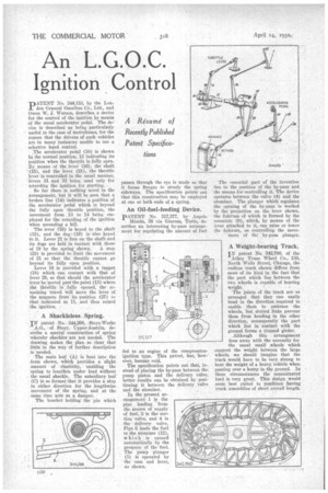
• The accelerator pedal (10) is shown in the normal position, 13 indicating its position -when the throttle is fully open. By means of the lever (16), the shaft (15), and the lever (21), the throttle lever is controlled in the usual manner, levers 31 and 33 being used only for retarding the ignition for starting. So far there is nothing novel in the arrangement, but it will be seen that a broken line (14) indicates a poSition of the accelerator pedal which is beyond the fully open throttle position, the movement from 13 to 14 being employed for the retarding of the ignition when ascending a hill. The lever' (16) is keyed to the shaft (15), and the dog (19) is also keyed to it. Lever 21 is free on the shaft-and its dogs are held in contact with those of 19 by the spring shown. A stop (23) is provided to limit the movement of 21 so that the throttle cannot go beyond its fully open position. Lever 16 is provided with a tappet (18) which can contact with that of lever 29, so that should the accelerator lever be' moved past the point (13) where the throttle is • fully opened, the remaining travel Will move the lever of the magneto from its position (27) to that indicated at 11, and thus retard the ignition.
A Shackleless Spring.
IN patent No.344.298, Steyr-Werke
A.G., of . Steyr, Upper-Austria, describe a special construction :of spring whereby shackles are not needed. The drawing makes the plan. so clear. that little, in the way of further description is needed.
The main leaf (A) is bent into the form shown, which provides a slight . amount of elasticity, enabling the 'spring to lengthen under load without
• the usual shackle. The subsidiary leaf (C) is so formed that it provides a stop in either direction for the lengthwise movement of the spring, and at the Same time acts as a damper.
The bracket holding' the pin which passes through the eye is made so that it forms flanges to steady the spring sideways. The specification points out that this construction may be employed at one or both Mitts of a spring.
An Oil-fuel-feeding Device.
PATENT No. 317,377, by Angelo Minola, 38 via Giacosa, Turin, describes an interesting by-pass arrangement for regulating the amount of fuel fed to an engine of the compressionignition type: This patent, has, 'however, become void. The specification points out that, instead of placing the by-pass between the pump piston and the delivery valve, better results can be obtained by positioning it between the delivery valve and the atomizer.
In the present ar• rangement 1 is the pipe leading ,.' from the source of supply , of fuel, 2 is the suction valve, and 4 is thedelivery valve. Pipe 5. leads the fuel to -the atomizer (12), which is opened automatically by the pressure of the fuel. , The pump plunger (3) is' operated by ' the cam and lever,
as shown. . .
The essential part or the invention lies in the position of the by-pass and the means for controlling it. The device operates between the valve (4) and the atomizer. The plunger which regulatesthe opening of the by-pass is worked by the projection on the lever shown, the fulcrum of which is formed by the eccentric (9), which, by means of the lever attached to it, can raise or lower the fulcrum, so controlling the move
ment of the by-pass plunger.
A Weight-bearing Track.
IN patent No. 342,760, of the Athey Truss Wheel Co., 130, North Wells Street, Chicago, the endless track shown differs from most of its kind in the fact that the part which lies between the two wheels is capable of bearing weight. The joints of the track are so arranged that they can easily bend in the direction required to enable them to embrace the wheels, but slotted links prevent them from bending in the other direction, consequently the part which lies in contact with the ground forms a trussed girder. Although this arrangement does away with the necessity for the usual small wheels which support the weight between the large wheels, we should imagine • that the track would have to be very strong to bear the weight of a heavy vehicle when Passing over a hump in the ground. In these circumstances the' concentrated load is very great. This design would seem best silted to machines having track assemblies' of short overall length.