


Patents Completed.
Page 22
If you've noticed an error in this article please click here to report it so we can fix it.
STOP VALVE. — Hopkinson and Others.—No. 27,450, dated 3rd December, 1906.—In order that pressure may be relieved from the egress side of the valve (B) when the valve is closed, the valve is operatively connected with a spindle (D). On this spindle is a disc valve (E) cooperating with ports (K, L), the former of
which communicates with the passage closed by the valve (B) on the egress side of the same, whilst the latter communicates with the atmosphere. The ports are so arranged that, when the valve is closed, the ports (K, L) are made to communicate
with each other, whilst, when the valve is open, this communication is interrupted.
DOUBLE GLAND. — Viney. — No. 20,263, dated 12th September, 1906.—In
an engine, where the glands and other Parts are mounted in an oil bath, it is desirable to so form the glands that steam will not pass out on the one side, nor oil on the other. For this purpose each gland comprises a chamber (f) which is connected by a sleeve (e) to a screwthreaded socket (di). This socket carries a closing piece for the chamber of the first gland (1), and a closing piece (g) is provided for the second gland, and is held in place by a cap (h). A conduit communicates with the chamber (f) at k and a way (j) is made through the wall of the chamber whereby the part (k) is put into communication with the space (i) situated between the socket (di) and the end of the gland chamber (f). From the passage (k) a conduit may extend to the exterior of the oil bath so that, should any leak occur past either of the glands, the operator may have knowledge of the same. If the gland (f) is leaking, steam will pass out by the passage (k), and if the gland (d1) is leaking, oil will pass out through the passage.
PISTON RODS.—Barker.—No. 28,841, dated 18th December, 1906.—For connecting the piston rod (B) to the head (A), the latter is provided with a diaphragm (D) having a central boss, and the rod (B) has a cup-shaped end (B1) adapted to engage this boss. The parts are kept in place by a disc (E) and annular nut (F). The nut leads into the head (A) by a screw-thread and maintains the disc against the exterior of the cupped end (B1) of the rod, whereby the parts are kept in proper relative position. The rod (13) is hollow, and the boss in the diaphragm (D) is perforated so that lubricant may pas by way of the conduit (G) through the boss to the crank (C).
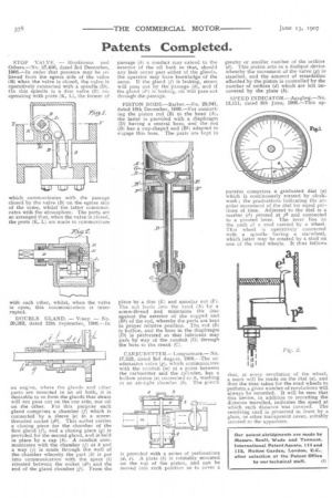
CARBURETTER.—Longuemare.— No. 17,523, dated 3rd August, 1906.—The air admission valve (g), which communicates with the conduit (m) at a point between the carburetter and the cylinder, has a hollow piston (a) connected to it, working in an air-tight chamber (b). The piston is provided with a series of perforations (d, e). A plate (k) is rotatably mounted on the top of the piston, and can be moved into such position as to cover a greater or smaller number of the orifices (el). This piston acts as a dashpot device whereby the movement of the valve (g) is steadied, and the amount of retardation afforded by the piston is controlled by the number of orifices (d) which are left uncovered by the plate (k).
SPEED INDICATOR.—Agagbeg.—No. 13,111, dated 6th June, 1906.—This ap
paratus comprises a graduated dial (a) which is continuously rotated by clockwork ; the graduations indicating the angular movement of the dial for equal portions of time. Adjacent to the dial is a marker (el) pivoted at p2 and connected to a pivoted lever. The lever lies in the path of a stud carried by a wheel. This wheel is operatively connected with a spindle having a starwheel, which latter may be rotated by a stud on one of the road wheels. It thus follows that, at every revolution of the wheel, a mark will be made on the dial (a), and thus the time taken for the road wheels to perform a given number of revolutions will always be recorded. It will be seen that this device, in addition to recording the distance travelled, indicates the speed at which such distance was covered. The revolving card is protected in front by a glass, or other transparent cover, suitably secured to the apparatus.