


Tractor-trailer Outfit for Rough Ground
Page 36
If you've noticed an error in this article please click here to report it so we can fix it.
A Resume of Recently Published Patent Specifications
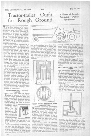
WHEN opeiating over rough ground, VV it is quite possible for a tractor vehicle to lose its driving grip, owing to its load being relieved by a change Of level. To deal with conditions of this nature is the object of a coupliro, system shown in patent No. 568,922 by L. Simmons, Jackson, Mississippi, U.S.A. This inventor describes a coupling arrangement by which the load on the tractor can be varied by hydraulic means, so as to obtain driving adhesion in ail circumstances.
The drawing shows sufficient ,of a tractor-trailer outfit to illustrate the principle involved. The tractor is of conventional form, and only the rear wheels (I) are shown. The trailer is provided with four wheels, two of which are mounted ordinarily, whilst the front pair (2) is carried by a swivelling front axle. The drawbar (3) is upswept to clear the tractor rear wheels -when short turns are being made. It is attached to the tractor through the medium of an enclosed ball-and-socket joint, whilst at the rear end it is pivoted on to the front axle of the trailer.
• Between the drawbar and the trailer axle is an hydraulic cylinder (4), the duty of which is to load the tractor to any desired degree by attempting to lift the front wheels of the trailer. The hydraulic cylinder exerts a force between a pivot on the drawbar and an extension (5) from the axle, and can, if worked to its limit, lift the wheels entirely from the ground and so convert the outfit into a semi-trailer. An adjustable screw and nut (6) enables any desired position to be maintained without the need for keeping a static pressure in the cylinder.
• HIGH-CONDUCTIVITY BRAKE FACINGS
THE most usual basis of friction facings is asbestos in some form, and this, whilst possessing good frictional properties, is a poor conductor of heat. The result is that the bulk of the heat has to be dissipated via the metallic member (the drum in the case of brakes), with consequent t e ndency for overheating to destructively high temperatures. To dispose of the heat more readily is the object of a friction facing having high conductivity described in patent No. 568,795, by the S. K. Wellman Co.. Cleveland, Ohio, U.S.A.
The material used is all-metallic, and the, shoes and the drum are similarly treated. The drawing shows a section of both, in which it will be seen that each facing consists of three layers; these are, first, a backing-strip of steel,
„M:rg seaTs
then an intermediate layer of an alloy having a predominance of copper, on top of which is the outer working face consisting of iron alloy, possibly containing some copper and graphite. In the case of the drum, a fourth layer of thin copper may be placed between the steel strip and the drum, the object being to check the formation of local hot-spots.
PISTON WITH IMPROVED HEAT CONDUCTIVITY A PISTON suitable for compressionPl. ignition engines and others subject to high-combustion ksrnperatures is shown in patent No. 568,599, by Specialloid, Ltd., and E. Graham, both of Frfern Park, London, N.12. The scheme eniploys a number of ribs to conduct the heat away from the centre of the crown, the area which usually has to bear the brunt of the high temperature. The drawing shows an oil-engine piston, in which the combustion space takes the form of a recess in the crown. From the underside of the crown: there extends a series of parallel ribs (1) which are -taper in section, so as to perrnit of theni being manufactured by
pressing. Further ribs (2) connect the piston crown with the, gudgeon-pin , bosses, mainly for mechanical reasons. A third set of ribs (3) is also provided; these are located on the inside face of the skirt and extend in a peripheral direction as far as the gudgeon bosses will permit. In height, they extend frorri the lowest compression ring down to the scraper-ring region.
Several alloys are suggested for the piston; high-silicon proprietary brands being specifically mentioned. Another suggestion is for an alloy containing cerium.
HEAT-PROTECTION FOR VALVE STEMS
TOprevent heat damage to the stem of an exhaust valve is the object of a small modification in design shown in patent No. 568,940, by J. Haefeli and the Austin Motor Co., Ltd., both of Longbridge Works, Birmingham. It is proposed to surround the exposed
portion of stem by a shroud so that there is no actual contact with the valve stem. The drawing shows the scheme applied to an overhead-valve engine, although it is, of course, equally applicable to side valves. In the example shown, the valve-guide housing is
screwed for the reception of the threaded end of the shroud (1). Thelatter may be made of metal, or of porcelain or other refractory material. The shroud does not fit the valve, and is in no wayan extended guide. An alternative scheme shows the cylinder casting itself extended to serve the same -purpose.