


IIMPLE MECHANICS Brakes-2
Page 49
If you've noticed an error in this article please click here to report it so we can fix it.
E HYDRAULIC brake sysrt, fitted to practically all irate motor cars and light nmercial vehicles, conts of a fluid tank or reserir, a master cylinder, and es to carry the fluid under issure from the master inder to wheel cylinders each wheel. Pistons in the ieel cylinders operate the ike shoes or disc pads. The out of a typical system is strated in Figure 1.
It will be seen that rigid and Oble pipes are both used, the ter being necessary to ;ommodate the up and down ivements of the road wheels d, in the case of the front as, to allow the wheels to steered.
The brake pedal operates a ton in the master cylinder, ich forces fluid into the pipe a, which already contains cr. The resulting increase in issure acts on pistons in each the wheel cylinders. These tons are in contact with the ike shoes (or pads in the case disc brakes), moving them yards the drums or discs.
This hydraulic operation has advantage of automatic Ike compensation because pressure on each cylinder is same; it also eliminates the ;ton present in a brake sysn with mechanical linkage. ere are, however, the folwing disadvantages.
Air, unlike a liquid, is readily mpressible, so, if air is
allowed to enter the system, air bubbles will have to be compressed before the brakes will operate. This will give the brake pedal a -spongy" feeling and result in reduced braking efficiency.
This is not a serious problem, as in normal circumstances there is no way in which air can enter the system. If it does, it can be easily expelled by -bleeding the system'', a special nozzle is provided near each wheel cylinder to facilitate this operation.
(2) Any serious leakage in the system will cause a complete failure of the brake. On modern vehicles this hazard is eliminated, or at least reduced, by fitting a system whereby, if a leak occurs, the brakes on at least half the wheels remain operative.
(3) A separate mechanical connection for the handbrake is necessary.
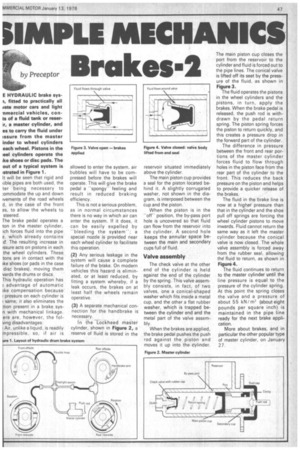
In i he Lockheed master cylinder, shown in Figure 2, a reserve of fluid is stored in the
reservoir situated immediately above the cylinder.
The main piston cup provides a seal for the piston located behind it. A slightly corrugated washer, not shown in the diagram, is interposed between the cup and the piston.
When the piston is in the "offposition. the by-pass port hole is uncovered so that fluid can flow from the reservoir into the cylinder. A second hole keeps the annular space between the main and secondary cups full of fluid.
Valve assembly
The check valve at the other end of the cylinder is held against the end of the cylinder by the spring. This valve assembly consists, in fact, of two valves, one a conical-shaped washer which fits inside a metal cup, and the other a flat rubber washer, which is trapped between the cylinder end and the metal part of the valve assembly_ When the brakes are applied, the brake pedal pushes the push rod against the piston and moves it up into the cylinder. The main piston cup closes the port from the reservoir to the cylinder and fluid is forced out to the pipe lines. The conical valve is lifted off its seat by the pressure of the fluid, as shown in Figure 3.
The fluid operates the pistons in the wheel cylinders and the pistons, in turn, apply the brakes. When the brake pedal is released, the push rod is withdrawn by the pedal return spring. The piston spring forces the piston to return quickly, and this creates a pressure drop in the forward part of the cylinder.
The difference in pressure between the front and rear portions of the master cylinder forces fluid to flow through holes in the piston face from the rear part of the cylinder to the front. This reduces the back pressure on the piston and helps to provide a quicker release of the brakes.
The fluid in the brake line is now at a higher pressure than that in the cylinder and the shoe pull off springs are forcing the wheel cylinder pistons to move inwards. Fluid cannot return the same way as it left the master cylinder because the conical valve is now closed. The whole valve assembly is forced away from the rubber seal, allowing the fluid to return, as shown in Figure 4.
The fluid continues to return to the master cylinder until the line pressure is equal to the pressure of the cylinder spring.
At this point the spring closes the valve and a pressure of about 55 kNIm' (about eight pounds per square inch) is maintained in the pipe line ready for the next brake application.
More about brakes, and in particular the other popular type of master cylinder, on January 27_