


World Ideas for Brake Improvement Home, Continental and American Inventions of Recent Announcement for En hancing the Efficiency of Brake
Page 25

Page 26
If you've noticed an error in this article please click here to report it so we can fix it.
Systems
STUDENTS of design cannot fail to have noted that of recent times one of the most outstanding respects in which commercial vehicles have shown improvement has been that of braking. In this specific field inventors have been particularly active, and it is no less notable that their efforts have been in no way stifled or restricted by the outbreak of hostilities.
These facts have been so clearly _ manifested by recently published patent specifications, originating from many different countries, that we have selected a representative group and present succinct summaries of them for the interest and information of our readers on this and the following page.
SENSITIVE CONTROL OF POWER BRAKING
T°give the driver a certain indication of the degree of braking being applied is the object of a control valve shown in patent No. 515,440. The patentees are E. Ottaway, S. Willett, London Passenger Transport Board, and Clayton Dewandre Co., Ltd., Titanic Works, Lincoln. In this scheme, the driver's effort is divided into two distinct stages—light braking, in which the distance traversed by the pedal is the chief indication, and a • heavier stage in which the resistance of tl-e pedal denotes the degree of braking.
The drawing shows the control valve, which is operated by moving the plunger (1) to the right The compressed air is supplied to port 6, whilst opening 4 leads to the brake cylinders. An atmospheric port (3) provides for the release of the brakes. Communication between the air supply and the brake cylinders is via valve 5.
In operation, plunger 1 compresses spring 9 which, in turn, moves piston 7 to open valve 5, the release port (8) being closed off in the process. When the air pressure on the piston (7) reaches a certain value, it overcomes the spring (9) and recloses the valve. So far the driver feels only spring 9.
Further movement of the pedal, however, causes the plunger (1) to meet a more powerful spring (2) and at this stage the effort of the driver must be suddenly increased. Spring 2 ,does not tend to move the piston (7), but is provided only for the purpose of forming a definite demarcation in the braking range. Extra loading for the piston is provided by spring 10. PREVENTING DEPRESSIONS IN HYDRAULIC SYSTEMS wThEN an hydraulic brake can alterVY natively be worked by mechanical' means, there is. a risk that during the operation by the latter means the disturbance of the fluid system may result in air being drawn in. To avoid this is the object of a design shown in patent No. 515,225 by Bendix, Ltd., and G. Roberts, both of King's Road, Tyseley, Birmingham.
In the drawing, the shoes are normally separated by outward movement of a pair of hydraulic pistons (4), or they may be moved by mechanical rotation of a cam (5). When the latter is used, the displacement of the sliding plungers (3) increases the volume of the cylinder, and might suck in air via any small leak. To avoid this, a chamber (1), in communication with the cylinder, houses a flexible bag (2) which is open to the atmosphere on one of its ends. When the cylinder pressure tends to fall, this bag unfolds and restores it to normal. The drawing shows the apparatus in the act of being mechanically operated. A BREAK-AWAY VALVE FOR TRAILER BRAKES
FROM Robert Bosch G.m.b.H., Stuttgart, Germany, comes patent No. 515,434, disclosing details of a control valve for compressed-air trailer brakes. The system is of the type in which a compressed-air container is carried on the trailer, and the brake valve is opened by a pressure drop in the tractor pipe, so that a breakaway would apply the brakes. The actual patent refers to 'a small manual valve
on the trailer for controlling its brakes when uncoupled.
In operation, a fall of pressure in the tractor pipe (1) upsets the balance of pressure between the two pistons (2 and 4) and causes them to move downwards, under pressure from the tank (3). The downward movement opens a valve (5) and supplies air to the brake cylinder (6).
To unbrake the trailer in these circumstances, a manual valve (9) can be operated to discharge the brake cylinder to the atmosphere, and re-connect it to the pressure tank if the braking be again required.
PROPORTIONING BRAKING FORCE TO LOAD •
A SCHEME for automatically adjust.ing the degree of braking to suit the weight of the load forms the subject of patent No. 514,192 from R Majert and others, of Kassel-Bettenhausen, Germany.
The design is applicable to brakes operated by compressed air, and employs a pressure-regulating valve which is governed by the load on the springs of the vehicle. The drawing indicates the basic principle, although the actual construction may be different. The air supply to the brake cylinder (2) passes through a pressureregulating valve (1) operated by a lever, the deflection of which is controlled by the load on the springs.
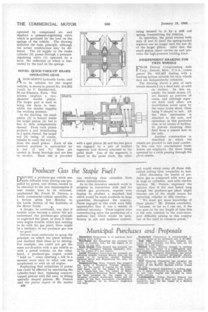
NOVEL QUICK-TAKE-UP BRAKE OPERATING GEAR
ANON-SERVO hydraulic brake, said to be suitable for the • largest vehicles, is shown in patent No. 514,872 (void) by V. Dachkevitch, 56 rue Eraeriau, Paris. The scheme employs a twodiameter master piston. The larger part is used to bring the shoes to bear, whilst the smaller supplies the working pressure.
In the drawing, the small piston (3) •is housed inside the larger piston (2) but is free to slide independently thereof. From each piston projects a .rod terminating in a quick thread, the larger rod (4) being, of course, tubular to carry the rod (1) from the small piston. Each of the screwed portions is surrounded by a nut (5. and 7); these are carried in frame bearings and are free to revolve. Each nut is provided with a spur pinion (6) and the two gears are engaged by a pair of toothed segments (not shown) attached to the pedal shaft. One of the segments is keyed to the pedal shaft, the other being secured to it by a stiff coil spring, transmitting the rotation. In operation, the pedal rotates both nuts (5 and 7) until the •spring-loaded segment can no longer turn the nut (5) of the larger piston: After this, the small piston alone carries •on and provides the high-pressure braking force.
INDEPENDENT BRAKING FOR TWIN WHEELS ROM Detroit Compensating Axle
Corp., Detroit, Mich., U.S.A., comes patent No. 515,057 dealing with a braking system suitable for twin wheels that are independently rotatable.
The drawing shows a pair of such wheels mounted on a dead axle, as used on trailers. In this example, the brake drums (1) are formed as portions of cones, and although separate from each other, are nevertheless 'acted upon by the same brake shoes, these being V-shaped to suit. All the shoe mechanism is attached to the axle, and operation, in this particular case, is by means of hydraulic pistons receiving their fluid from a central hole in the axle.
Another construction is described in which the wheels are pivoted to suit road camber. In this case two conventional brake drums are employed, the shoes being operated by a cable passing through the pivot centre.