


Patents Completed.
Page 22
If you've noticed an error in this article please click here to report it so we can fix it.
Complete specifications of the following patents will be sent to any address in the United Kingdom upon receipt of eightpence per copy at the Sale Branch, Patent Office, Holborn, W.C.
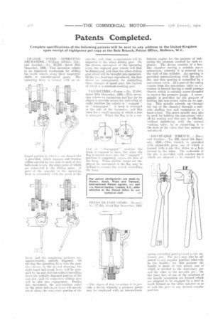
CHANGE SPEED OPERATINU MECHANISM.—William Allchin, Ltd., and Another.—No. 28,234, dated 28th Deeember, 1908.—This invention relates to an improved mechanism for sliding the tooth wheels along their respective shafts in variable-speed gears. The operating lever is funned with an en larged portion in which a cam shaped slut is provided. which engages anti-friction rollers carried by one arm of each of two boll-crank levers. the other arms of which are eurtnveted to the sliding gears. A part of tht cam-slot hi the operating lever is concentric with the pivot eflie lever, mid the remaining portions are, approximately, radian:. disposed. On moving the operating lever into the position b.iaiwn in the second drawing, the right hand bell-crank lever will he actuated by its anti-friction roller's travelling down the radially-disposed portion of the cam•slet. and its respective sliding gear will be slid into engagement. During this nievement. the anti-friction roller oh the other bell-crank lever will merely travel alone the concentric portion of the
cam-slot, and, thus no movement will be imparted to the other sliding gear. On the reverse movement of the operating lever, the engaged gear wheels will first be disengaged, and then the other sliding gear wheel will be brought into operation. Of the two drawings reproduced, the first shows an arrangement for controlling three changes of speed gear, the highest of which is a constant-meshing gear.
TA X I M ETERS.—Foster .—No. 27,644, dated path December, 1908.—This invention relates to taximeters and has for its object to provide means for indicating at night whether the vehicle is " engaged " disengaged.A lamp is arranged at the side of the taximeter, and this lamp has a small opening in which a lens is arranged. When the flag is in a ver
tieal hr disengaged " position the lainp is exposed to view, but when the flag is turned dewn into the " engaged " position it completely covers the lens of the lamp. When electric lamps are employed the movement if the flag may be utilised ii ictuate the switch controlling the holm.
—The object of this iitvention is to pro vide a device whereby a pressure gauge may be employed with au internal-com
bustion engine for the purpose of indicating the pressure exerted by each explosion. The device consists of a boxlike chamber having a suitable screw connection, whereby it is screwed into the wall of the cylinder. An opening isprovided communicating with the cythider, and this opening is controlled by a non-rcturn valve. At a part of the casing, remote from the non-return valve an extension is formed having a small passage therein which is suitably screw-threaded to receive the pressure gauge. A screwspindle is provided for the purpose of holding the non-return valve on its seating. This spindle extends up through the top of the chamber through a suitable stuffing box and terminates in a hand-wheel. The screw-spindle may also. be used for holding the non-return vahe off its seating and this may be effected. without interfering with the normal working valve, by so connecting it to. the stem of the valve that lost motion is ntrod aced.
ADJUSTABLE WRENCH. — Perry and Another.—No. 239, dated 5th January, 1909.—This wrench is provided with adjustable jaws, one of which is formed with a pin that slides in a hole formed in the other. The underside if the phi is provided with ratchet teeth wltich are adapted to be engaged by a.
snring-eootrolied pawl pivoted to the .sta tionary jaw, The jaws may also be adjusted to roy angular' position relatively to the hamile ; for this purpose the handle is made in two pieces, one ol" which is pivoted to the stationary jaw and the other to the movable jaw. Oil the inner face of one of the members of the handle serrations are formed which are adapted to be engaged by a heel ol tooth formed on the other member so as to lock the jaws in any desired angulai • posit ion,