


Adapting Implement-lift Ram for jacking Up Tractor
Page 36
If you've noticed an error in this article please click here to report it so we can fix it.
A Résumé of Patent Specifications That Have Recently Been Published
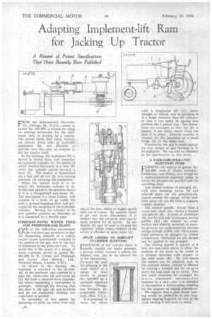
FROM the International. harvester CO., Chicago, Ill., U.S.A., comes, in • patent No. 541,979, a scheme for using an. existing mechanism for the additional duty of jacking up. a tractor. The patent states that many tractors are already fitted with an hydraulic,. inkplenient lift, and pi-oceeds to' describe how, this may be adapted to lift the tractor itself.
In the drawing, the implement lift is shown in dotted lines, and comprises an hydraulic cylinder ( I) the piston of which remains stationary in a tube (3) while the cylinder movesforward a lever (7): The motion istransmitted via afore and aft rod '(2) to a rocking platform (4) Carrying the. implement. –When the tractor itself is to be raised,' the hydraulic cylinder is detached and placed in the position shOwn at 6 in a triangulated jack-frame (5). The last-named is a loose fitment, and consists of a hook to go under the axle, a ground-engaging shoe, and provision for the reception of the hydraulic cylinder. Moving the cylinder to its new position presents no difficulty, as it is connected by a flexible pipe.
CONSTANT-RATIO WATER FEED FOR PRODUCE R.GAS. PLANT
ONE of the difficulties encountered ‘..../with wet-blast gas producers is that the fluctuating demand of a vehicle. engine causes considerable variation in the quality of the gas, due to the lack of constancy in the water-air ratio. To avoid this is the object of a design of water vapOrizer shown inpatent No. 541,836 by. E. CoWan and Parkinson and Cowan (Gas Meters), • Ltd., Terrhinal House, London, S.W.1.
As shown in the drawing, the vapOrizer is attached to the air-inlet (6) of the producer, and consists of a pipe (4), choke-tube (2) and water jet (1) fed from a chnstant-level chamber; the -whole resembling a carburetter in principle. Although the drawing does not show it, the pipe (4) and. its 'choke and jet are duplicated, forming two vaporizers in parallel. .
In operation, at low speeds the incoming air picks up water from only one of the jets, whilst at higher speeds both are in action. By suitable choice of jet and choke dimensions, it is claimed that the aie-water ratio can be made uniform for all speeds. An 'airshutter (5) may be used to by-pass the vaporizer, whilst visual evidence of the action is afforded by glass tubes (3).
-SPLIT LINERS TO SIMPLIFY CYLINDER SLEEVING It is proposed to make the sleeve
with a lengthwise slit (1), either. straight Or helical, and to pre-form it to a larger diameter than the cylinder, so that it tan easily be sprung into position like a piston ring. The dimensions are arranged so, that the slit is • almost, if not quite,.. closed when the liner is in place. Endwise security is ensured by the provision of a small flange (2) at the upper end. Presumably the gap is small enough for any escape of gas through it to be negligible. We can find no reference ,in the .specification to this point.
A FACE-CAM.OPERATED INJECTION PUMP FORMING the subject ofpatent No. 541,885, from F. Stark, Avondale, Chellaston, near IDerby, fs.a desigit for a multi-CYlindered injection" pump iii winch the plungers are parallerwith the operating shaft.
_ Any desired number of plungers (5),
with their discharge . valves. (3) and take-off 'pipes (2) are peripherically spaced around the casing, whilSt their inlet ports (4) are fed from a common central chamber. ..
. The central spindle, driven from d. worm and wheel. (7), carries a formed cam-groove (6). A series of crossheads (9),one to each pair of plungers, having
guides (1 I ) arc shaped in crosssection and slida.bly mounted, ih annular grooves, are reciprocated by the cam acting through rollers (1.0).Each crosshead embraces its plungers by forked connections. ObVionsly no side :thrusts can be applied to the plungers...
r,The driving spindle is splined at ' into the cam-track sleeve to allow the position of the latter to be varied in a vertical direction' with respect to the inlet ports (4)'. By. this means the output can be adjusted, and, in the example shown, control is 'effected . by turning a knurled nut (1) so as to move the cam-track up or down. This nut could doubtless be' arranged for more convenient opera tion—f .instance by a rack—also it is intended to incorporate a helical-spline coupling for the 'purpose of timing adjustment.
We suggest that a pure-thrust hearing would be preferable-, to the deepgroove bearing depicted, in view of the axial loading it will have to stand.