


SAVING LOADING-TIME WASTE
Page 15
Page 16
If you've noticed an error in this article please click here to report it so we can fix it.
MANY BUSY MINDS have been at work on the problem of how to make the fullest possible use of the power unit of a motor lorry, aiming at efficiency equal, if not in fact superior, to that of the horse, which, whilst the van is being loaded or unloaded, can, in many instances, be taken away and put to another use. Bodies have been devised to facilitate loading and unloading, and so save some of the time that would otherwise be wasted through the motor power lying inert.. Detachable bodies, of which the LancasIVO:e "Flat' is typical, have been put into use in certain districts and by certain concerns, considerable economies having been effected and the capital charges in connection with the lorry having thereby been spread over a much greater tonnage. The difficulty about the Flat system is that a erase is required at each loading and unloading place in order to handle the bodies, and it is contended that time is unnecessarily wasted in getting the body correctly positioned and secured on the chassis.
Mr. C. W. Stamper's loading truck for motor lorries has been described by us briefly. Details of it have undergone development, and Mr. Stamper is now prepared to receive and execute orders for it. The system entails the use at each end of the journey of a separate truck on to which the body from the lorry can be transferred by means of a winch carried permanently on the motor chassis, the forecarriage df the loading truck being of the ordinary van type having a drawbar by which the truck and its load may be moved about.
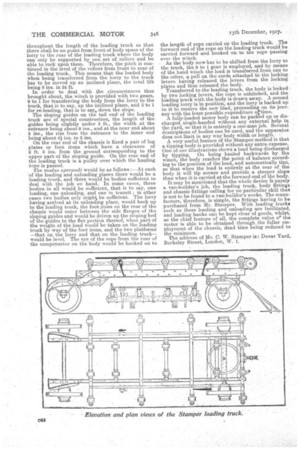
The four essential items of the system are the slipjug -guides at the tail end of the loading truck, the roller system, the locking levers and, the compensating mechanism.
The chassis of the lorry is provided with seven bearers, four of them having each four rollers, and the other three having each two rollers. On the underside of the body is positioned the compensator, which consists of a double pulley system, spring connected, the spring taking up the slack of the rope, and always maintaining that pull which is equivalent to the pull maintained by hand on a capstan rope. On the chassis are also pivoted four of the locking levers. The levers are pivoted on stump plates secured to the longitudinal bearers on the chassis, whilst .to the underside of the body are attached locking plates. As the body is drawn on to the lorry, the locking plates are able to ride over the head of the locking levers, and when the body is in position a pull on a rope attached to the lower ends of the locking levers engages the hook of each lever with its locking plate so that the levers securely hold the body against movement in any direction. On the under side of the-body there are also four angle irons fixed •lengthwise, which act as runners and guides, preventing any movement of the body sideways on the chassis whilst it is being transferred from lorry to loading truck or vice-versa.
The loading truck consists of a framework equipped with seven sets ef rollers exactly the same as the Motor lorry. At the rear end is a fixed axle placed immediately below the sloping guides. At the fore end, as we have already mentioned, there is an ordinary van forecarriage. The pitch of the chassis on a motor lorry fully loaded is about 4 ins. in 12 ft. It is obvious that this pitch -must be continued
throughout the length of the loading truck so that there shall be no point from front of body space of the lorry to the rear of the loading truck where the body can only be supported by one, set of rollers and be able to rock upon them. Therefore, the pitch is continued in the level of the rollers from front to rear of the loading truck.. This means that the loaded body when being transferred from the lorry to the truck has to be moved up an inclined plane, the total lift being 8 ins. in 24 ft.
In order to deal with the circumstances thus brought about, the winch is provided with two gears, 9 to 1 for transferring the body from the lorry to the truck, that is to say, up the inclined plane, and 3 to 1 for re-loading, that is to say, down the slope.
The sloping guides on the tail end of the loading truck are of special construction, the length of the guides being slightly under 3 ft., the width at the entrance beingabout 9 ins., and at the near end about 5 ins., the rise from the entrance to the inner end being about 4 ins. to 5 ins. • On the rear end of the chassis is fixed a pair of lug plates or foot irons which have a clearance of 2 ft. 3 ins, from the ground corresponding to the upper part of the sloping guide. On the rear end of the loading truck is a pulley over which the hauling rope is passed.
The modua operandi would be as follows : —At each of the loading and unloading places there would be a loading truck, and there would be bodies sufficient to deal with the job on hand. In some cases, three bodies in all would be sufficient,. that is to say, one loading, one unloading, and one in transit ; in other cases two bodies only mighti be sufficient The lorry having arrived at its unloading place, would back up to the loading truck, the foot irons on the rear of the chassis would enter between the side flanges of the sloping guides and would be driven up the sloping bed of the guides to the flat portion thereof, when part of the weight of the load would be taken on the loading truck by way of the foot irons, and the two platforms —that on the lorry and that on the loading truck— would be level. The eye of the rope from the rear of the compensator on the body would be hooked on to
the length of rope carried on the loading truck. The forward end of the rope on the loading truck would be carried forward and hooked on to the rope passing over the winch. As the body now has to be shifted from the lorry to the truck, the 9 to 1 gear is employed, and by means of the hand winch the load is transferred from one to the other, a pull on the cords attached to the locking levers having released the levers from the locking plates and thus released the body. •
Transferred to the loading truck, the body is locked by two locking levers, the rope is unhitched, and the loading truck with the body is drawn away.. A second loading lorry is in position, and the lorry is backed up to it to receive the new load, proceeding on its journey with the least Possible expenditure °Virile,
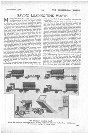
A fully-loaded motor body can be packed up or discharged single-handed without any external help in the yard„ so that it is entirely a one-man job. Several descriptions of bodies can be used, and the apparatus does not limit in any way body width or length. A very useful feature of the Stamper method is that a tipping body is provided without any extra expense. One of our illustrations shows a load being discharged by tipping. On being hauled backwards by the winch, the body reaches the point of balance according to the position of the load, and automatically tips, so that when the load is entirely at the rear of the body it will tip sooner and provide a steeper slope than when it is carried at the forward end of the body.
It may be mentioned that the whole device Is purely a van-builder's job, the loading truck, body fittings and chassis fittings calling for no particular skill that is not to be found in a van-builder's works. The manufacture, therefore, is simple, the fittings having to be purchased from Mr. Stamper. With loading trucks such as these loading and unloading are facilitated, and loading banks can be kept clear of goods, whilst, as the chief feature of all, the complete value & the motor is able to be obtained through the fuller employment of the chassis, dead time being reduced to the minimum.
The address of Mr. C. W. Stamper is: Dover Yard,. Berkeley Street, London, W. 1.