


ADJUSTING A PISTON TO THE CYLINDER BORE.
Page 70
If you've noticed an error in this article please click here to report it so we can fix it.
A Résumé of Recently Published Patent Specifications.
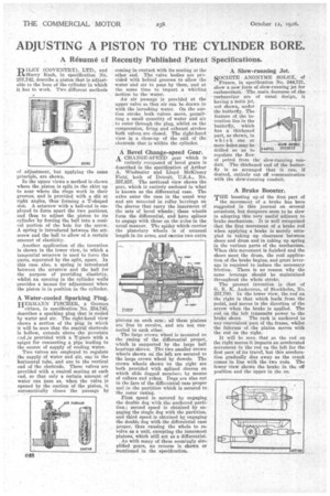
-ID 'LET (COVENTRY), LTD., and _IA/Harry Rush, in specification No. 257,742, describe .a piston that is adjustable to the bore of the cylinder in which it has to work. Two different methods
of adjustment, but applying the same principle, are shown.
In the upper views a method is shown where the piston is split in the skirt up to near where the rings work in their grooves, and is provided with a slit at right angles, thus forming a T-shaped slot. A setscrew with•a hall-end is employed to force apart the two portions, and thus to adjust the piston to its cylinder by forcing the ball into a conical portion of the hole for the screw. A spring is introduced between the setscrew and the ball to allow of a certain amount of elasticity.
Another application of the invention is shown in the lower view, in which a tangential setscrew is used to force the parts, separated by the split, apart. In this case also, a spring is introduced between the setscrew and the ball for the purpose of providing elasticity, whilst an opening in the cylinder walls provides a means for adjustment when the piston is in position in the cylinder.
A Water-cooled Sparking Plug.
HERMANN F1SCEEER, a German citizen, in specification No. 254,745, describes a sparking plug that is cooled by water and air. The right-hand view shows a section of the plug' in which it will be seen that the central electrode is hollow, extends above the porcelain rAid.is provided with a T-piece with a spigot for connecting a pipe leading to the source of supply of cooling water.
Two valves are employed to regulate the supply of water and air, one in the horizontal tube, and one in the vertical end of the electrode. These valves are provided with a conical seating at each end, so that only a certain amount of water can pass as, when the valve is opened by the suction of the piston, it automatically closes the passage by coming in contact with its seating at the other end. The valve bodies are provided with helical grooves to allow the water and air to pass. by them, and at the same time to impart a whirling motion to the water.
An air passage is provided at the upper valve so that air can be drawn in with the inrushing water. On the suction stroke both valves move, permitting a small quantity of water and air to enter through the plug, whilst on the compression, firing and exhaust strokes both valves,are closed. The right-hand view is a close-up of the end of the electrode that is within the cylinder.
A Bevel Change-speed Gear,
A CHANGE-SPEED gear which is entirely composed of bevel gears is described in the specification of Arthur A. Wiedmaier and Lloyd McKinfsey Field, both of Detroit, U.S.A., No. 257,837. The sectional view shows the gear, which is entirely enclosed in what is known as the differential case. The axles enter the case in the usual way and are mounted in roller bearings on the sleeves that carry the innermost of the sets of bevel wheels; these wheels form the differential, and have splines to engage with those On the axles in the usual manner. The spider which carries the planetary wheels is of unusual length-in its arms, and carries two extra
pinions on each arm; all these pinions are free to revolve, and are not connected to each other.
The large Crown wheel is mounted On the casing of the differential proper, which is supported by the large ball bearings shown. The two smaller crown wheels shown OD the left are secured to the large crown wheel by dowels. The crown wheels shown On the right are both provided with spline(' sleeves on which slide dogged members by means of collars and yokes. Dogs are also cut in the face of the diffezehtial case proper and in the partition which is secured to the outer casing.
First speed is secured by engaging the double dog with the anchored partition; second speed is obtained by engaging the single dog with the partition, and third speed is obtained by engaging the double dog with the differential case proper, thus causing the whole to revolve as a unit, excepting the innermost pinions, which still act as a differential.
As with many of these seemingly simplified gears, no reverse is shown or mentioned in the specification.
A Slow-running Jet.
SOCIETE ANONYME SOLES, of France, in specification No. 244,721, show a new form of slow-running jet for carburetters. The main features of the carburetter are of usual design, it having a main jet, not shown, under the butterfly. The feature of the invention lies in the butterfly, which has a thickened part, as shown, in which one or more holes may be drilled so as to regulate the flow
of petrol from the" slow-running conduit. The thickened end of the butterfly is so arranged that it .Can, if desired, entirely cut off communication with the slow-running conduit.
A Brake Booster.
THE boosting upof the first part of the movement -of a brake has been suggested in this journal on several occasions, but designers seem to be slow in adopting this very useful adjunct to brake mechanism. It is well recognized that the first movement of a brake rod when applying a brake is merely occupied in taking Up clearance betvmen shoes and drum and in taking up spring in the various parts of the mechanism. When this movement is finished and the shoes meet the drum, the real application of the brake begins, and great leverage is required to induce the necessary friction. There is no reason why the same leverage should be maintained throughout the whole stroke.
The present invention is that of G. K. K. Andersson, of Stockholm, No. 257,780. In the lower view, the rod on the right iS that which leads from the pedal, and moves in the direction of the arrow when the brake is applied. The rod on the left transmits power to the brake shoes. The rack is anchored to any'convenient part of the frame, whilst the fulcrum • of the pinion moves with the rod on the right.
It will be seen that as the rod on the right-moves it imparts an accelerated movement to' the rod on the left for the first part of its travel, but this acceleration gradually dies away as the crank comes in line with the two rods. The lower view shows the •brake in the off position and the upper in the on.