


Novelty in Opposed Piston Engine Design
Page 60
If you've noticed an error in this article please click here to report it so we can fix it.
A Résumé of Recently Published Patent Specifications
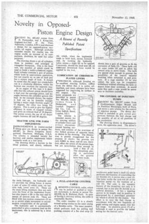
PATENT No. 602,662 comes from H. Penwarden, and J. Kingcome, Engineer-in-Chief of the Fleet, Admiralty, London, S.W.1;-and discloses a design for an opPosed-piston twostroke oil engine. Although probably intended mainly for marine use, the engine could, on account of its compactness, doubtless be used for other purposes. •
The drawing shows a set of cylinders, three in number; and arranged in triangular formation. This is the basic unit," any number of which could be used to build a multi-cylindered engine. Each Cylinder contains a pair of pistons which work -in approximate opposition, but not exactly so, as one of each pair has a certain angle of lead. It should be noted that the upper two crankshafts run in a clockwise direction, whilst the bottom one revolves the opposite way.
In an engine of this type it is desirable that the exhaust piston should have a lead over the scavenge piston, and the angles between the cylinders govern this lead. In the example shown, the engine is laid out on an isosceles triangle having a major angle (bottom angle) of 75 degrees, the other two being 52f degrees. This is said to give the highest efficiency in terms of trapped volume, and gives an exhaust lead of 10 degrees. The patent covers the use of all major angles between 60 and 90 degrees.
TRACTOR LINK FOR FARM IMPLEMENTS I MPROVEMENTS in tractor-carried lifting gear are shown in patent No. 602,887, by Harry Ferguson Incorporated, Dearborn, Michigan, U.S.A. The scheme is intended mainly for harrows and similar implements which normally work at a low level.
The drawing shows a harrow in the lifted position, and clearly indicates
the main linkages. An hydraulic unit (1) provides the lifting force; it moves a pair of arms (2) which raise, via tension rods, lower arms (3). These are the main lifting members; they not only raise the front of the implement frame, but also impart a lift to the rear end by means. of tension rods (4). These are fitted with lost-motion connectors (5) so as to permit slight movement to accommodate irregularities of the ground.
The hydraulic unit is automatically controlled to give a constant load on the implement; this is achieved by a lever
A34 (6), which, when the implement tends to hold back, moves forward and, by working the hydraulic valve, causes a slight lift to be applied. Conversely, should the load ease off, an additional downward force would be applied to the tool.
LUBRICATION OF CHROMIUM.PLATED LINERS
C"OMIUM, although forming an excellent wearing surface, suffers from the defect that it is rather oilrepellent, and many schemes have been suggested for improving its surface in this respect. The latest proposals are described in patent No 603,466, which comes from S.
-Hedgecock, a n d Laystall Engineering Co., Ltd., 53, Great Suffolk Street, London, S.E.1.
The scheme is intended mainly for the wearing surface of cylinder-liners and other chromiumtreated bearing surfaces, and consists of the provision of two helical grooves of opposite hand, as shown in the drawing. The illustration is greatly exaggerated for the purpose of clarity; the grooves are only 0.0001 in. deep, and do not, therefore, affect the action of the piston rings, but are nevertheless deep enough to
hold a film of oil. The chromium plating is performed after the grooves have been made.
A PULL-AND-PUSH CONTROL CABLE
AREMOTE-CONTROL cable, which can be pulled or pushed to transmit movement, is shown in patent No. 602,958, by IL Richoux, Paris. In spite of having a two-way action, the cable is reasonably flexible.
The outer member (1) is a closely wound spring similar to the outer casing of a Bowden cable. The inner member, which performs both the pulling and pushing, consists of a flat steel strip (2) drawn into a pair of grooves to fit the curvature of balls (3). These balls roll on outer tracks (4) and so allow the central strip to move freely. The bars are spaced close enough to prevent the possibility, of the central Member buckling when subjected to encI pressure. If a cage member (5) be also added, the wire can be completely withdrawn without allowing the balls to depart from their positions. It would seem that such a cage would be necessary to facilitate assemBly.
THE CONTROL OF INJECTION PUMPS
PATENT No. 604,597 comes from Etablissements Edgar Brandt and La Precision Mecanique, both of Paris, and shows a new scheme for the control of injection pumps. The device described is intended to give correct proportions between the fuel charge and the quantity of air at all positions of the accelerator.
The drawing ihows, in diagrammatic form, the apparatus used. The driver's accelerator pedal turns a shaft (1) which performs the function of controlling the air throttle (2); it carries also a cam (3). The latter works the rack-rod (4) of, the injection pump via the medium of a rod (5). The cam is the essential feature of the invention; not only is it rotated, but it can also be moved in an
endwise direction. It has a tapering section in its length, and its position is determined by a centrifugal governor (6) which-is driven by the engine. The effect is to vary the fuel charge in accordance with the two functions of pedal setting and engine speed, over the full range. An eccentric. pivot (7) of a bellcrank is used to provide the initial setting for the fuel-air ratio.