


Modified Two-Speed Axle
Page 52
If you've noticed an error in this article please click here to report it so we can fix it.
A Résumé of Recently Published Patent Specifications
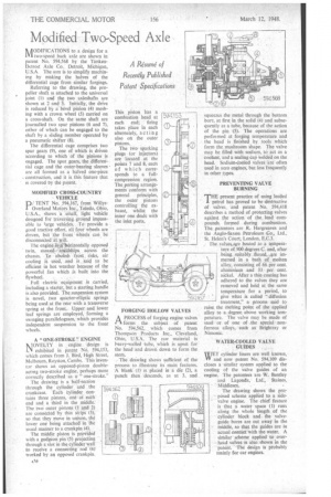
hfiODIFICATIONS to a design for a 'VI two-speed back axle are shown in patent No. 594,568 by the TimkenDetroit Axle Co., Detroit, Michigan, U.S.A.The aim is to simplify machining by making the halves of the differential cage from similar forgings.
Referring to the drawing, the propeller shaft is attached to the universal joint (1) and the two axleshafts are shown at 2 and 3. Initially, the drive is reduced by a bevel pinion (4) meshing with a crown wheel (5) carried on a cross-shaft. On the same shaft are journalled two spur pinions (6 and 7), either of which can be engaged to the shaft by a sliding member operated by a pneumatic shifter (8).
The differential cage comprises two spur gears (9), one of which is driven according to which of the pinions is engaged. The spur gears, the differential cage and the outer-bearing sleeves are all formed as a halved one-piece construction, and it is this feature that is covered by the patent.
MODIFIED CROSS-COUNTRY VEHICLE
P/ TENT No. 594,167, from Willys1 Overland Motors Inc., Toledo, Ohio, U.S.A., shows 'a lanai], light vehicle designed for traversing.ground impassable to large vehicles. To provide a good tractive effort, all four wheels are driven, but the front Wheels' can be disconnected zit. will.
The engine .is ,a ;horizontally opposed twin, stowed. 'idships across the chassis. To abolish frost risks, air cooling is used, and is said to be efficient in hot weather because of the powerful fan which is built into the flywheel. .
Full electric -equipment is carried, including a starter, but a starting handle is also provided. The suspension system is novel, two quarter-elliptic springs being used at the rear with a transverse spring at the front. Upper and lower leaf springs are employed, forming a swinging parallelogram, which provides independent suspension to the front wheels.
A " ONE-STROKE " ENGINE NIOVELTY in engine design is 1:44 exhibited in patent NO. 594,153, which comes from J. Bird, High Street, Melbourn, Royston, Cambs. This inVentar shows an opposed-piston doubleacting two-stroke engine, -perhaps more correctly described • as aone-stroke."
The drawing is a half-section through the cylinder and the crankcase. Each Cylinder contains three pistons, one at eath end and a third in the middle. The two outer pistons (1 and 2) are connected by thin strips (3), so that they Move in unison, the lower one being attached in the usual mariner to a crankpin (4).
The middle piston is provided with a gudgeon pin (5) projecting through a slot in the cylinder wall to receive a connecting 'rod (6)' worked by an opposed crankpin. FORGING HOLLOW VALVES
APROCESS of forging engine valves forms the subject of patent No. 594,562, which comes from Thompson Products Inc„ 'Cleveland, Ohio, U.S.A. The raw material is heavy-walled tube, which is upset for the head and drawn down to form the stem_.
The drawing shows sufficient of the process to illustrate its main features. -A blank'. (1) is placed in a die (2), a punch then descends, as at 3, and
squeezes the metal through the bottom bore, at first in the solid (4) and subsequently as a tube, because of the action of the pin (5). The operations are performed at forging temperature and the head is finished by, tools which form the mushroom shape. The valve may be filled with sodium, to act as a coolant, and a sealing cap welded on the head. Sodium-cooled valves are often used in aero engines, but less frequently in other types.
PREVENTING VALVE BURNING
T"present practice of using leaded petrol has proved to be destructive of valves, and patent No. 594,418 describes a method of protecting valves against the action of the lead compounds formed during combustion. The patentees are R. Hargreaves and the Anglo-Saxon Petroleum Co., Ltd., St. Helen's Court, London, E.C.3.
fhe valges..are heated to a. temperature of 900 degre,es C. and, after being .suitably tluxed„are immersed in a bath of molten alloy, consisting of 66 per cent. aluminium and 33 per cent. nickel. After a thin coating has adhered to the valves they are removed and held, at the same temperature for a period, to give what is called "diffusion treatment," a process said to raise the melting point of the applied alloy to a degree above working temperature. The valve may be made of steel or of tine of the special • nonferrous alloys, such as Brightray or Nirnonic.
WATER-COOLED VALVE GUIDES WET cylinder liners are well known, VV and now patent No. 594,109 discloses a similar system applied to the cooling of the valve guides of an engine. The patentees are W. Bentley and Lagonda, Ltd., Staines, • Middlesex.
The drawing shows the proposed scheme applied to a sidevalve engine. The chief feature is that a water space (1) runs along the whole length of the cylinder block and the valveguide bores are cut away in the Middle, so that the guides are in actual contact with the. water. A sinrilarscheme applied to overhead valves is also shown in the patent. 'The design is probably mainly for car engines.