


A Straussler Four-wheel-drive Vehicle
Page 54
If you've noticed an error in this article please click here to report it so we can fix it.
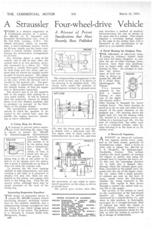
THERE is a distinct suggestion of 1 Continental practice in a patent, Nu. 460,465, by N. Straussler and Straussler Mechanization Ltd., both of 70, Pall Mall, London, S.W.1. The vehicle described, which is, presumably, a short-wheelbase tractor, drives on all four wheels, and the frame comprises a central tubular member containing the transmission arrangements to all axles.
The drawing shows a plan of the vehicle, and it will be seen that the central tube is in two portions, pivotally connected by a sleeve (2). This provides a virtual three-point support to both front and rear axles, and ensures that all wheels are equally loaded in spite of uneven ground. The engine (1) is supported on a frame bracket (3) at the rear, whilst the forward end_is carried by the gearbox (4). The gearbox casing is spherically mounted on the tubular chassis, so that the engine also is three-point supported.
The driver's seat is on the opposite side to the engine, thus making for a very short vehicle. It will be noticed that the bodywork (shown in dotted lines) is in two distinct portions; this is necessary on account of the flexibility of the tubular chassis.
The specification mentions another scheme in which the gearbox is attached to the central tube, near the middle, the engine, however, remaining as above described.
A Lining Ring for Pistons.
AN attempt to prevent piston expansion from distorting the upper ring is shown in patent No. 460,420 by Brandenburgische lielotorenwerke G.m.b.H., Berliner Chaussee,
The scheme is to fit the piston ring into a channel-section ring (1) which, in turn, is fitted into the piston groove. This lining ring is slit at one point to enable it to he sprung over the piston, but is given a contractile set so that it does not reach the cylinder wall.
To prevent the slit from opening slightly at high temperatures, and thus creating a gas leak, it is proposed to employ, two pins (2); these are embedded in the piston, and engage with holes in the lining. ring. Thus the slit cannot widen, although there may be ample clearance at the hack of the lining ring.
Interesting Suspension Equalizer.
THE design of suspension shown in patent No. 457,089 contains several interesting features, including torsion bars for the resilient members, and a compensating linkage arranged so that the rising of one wheel brings about the descent of the others. The patentee is L. Renault, 8, Avenue Emile Zola, Billancourt, France.
A36
and describes a method of similarly interconnecting the sets .of wheels on the same side of a vehicle. This scheme employs a reversing linkage applied to the ends of the torsion bars, and is illustrated in the specification as applied to a six-wheeled vehicle.
A Novel Bearing for Gudgeon Pins.
THE difficulties of effectively lubrieating an. ordinary bushed small end have led many designers to consider the use of roller bearings, these, however, have their own problems, such as larger bulk, and liability to damage by' heat. An attempt to combine the advantages of both systems is shown in patent No. 460,425 by I. Zeissl, -Starhemberggasse 16, Vienna.
T h e inventor proposes to employ a bushed bearing to take care of the slight side thrusts, with a roller bearing to transmit the heavy vertical forces. The latter bearing is novel in so far as only one roller is employed, of the same diameter . as the gudgeon pin. The drawing shows the upper bush (1), and the bearing roller (2), housed in a clearance recess, and rolling on a hardened pad (3). For the sake of compactness, the roller need not be a 'complete cylinder, other designs showing it in the form,of an Hsection strut.
A Heavy-on Vaporizer.
APATENT on heavy-oil carburetters appears nearly every week, and is, for some reason, generally of Scandinavian origin. Such a device is dealt with in patent No. 460,123 by S. E. Bengtson, 10, Batangsvagen, Stockholm, Sweden. This scheme employs the usual practice of starting the engine on petrol, and using the exhaust heat to vaporize the heavy oil. To this end, the vaporizing chamber (5) is built into a flanged tube, through which the exhaust gases pass. Fuel, controlled by the needle valve (2) passes into the top of the heater chamber (5), mixes with a small quantity of exhaust gas and, in the form of spray, passes down the bell-shaped member (4), being vaporized in the process. The vapour is then drawn through a venturi (9), mixed with air, and fed to the engine.
The novelty• of the scheme is based on the construction of the bell-shaped member (4). This can be moved downward by a control device (1), and when in this position, is thoroughly scavenged by a straight-through blast of exhaust gas when the engine is petrol driven. Another feature is the use of a highly-expansive metal for the bell, so that the carbon is cracked off by :a change of temperature.