


Brakes, 5
Page 34
If you've noticed an error in this article please click here to report it so we can fix it.
HAVING dealt with compressors in the last article, we can now consider how the air is stored. Air reservoirs on motor vehicles are of cylindrical form with domed ends. Sometimes one reservoir is divided so that it can provide air for two parts of the system. Each part is completely independent of the other and this arrangement gives the same degree of storage as if two completely separate tanks were used. The reservoirs are made of steel pressings welded together. Threaded bosses for the attachment of the input, output and other connections are provided.
As a safety precaution, it is necessary to provide some means of preventing all the air escaping when a leak occurs in one part of the system. In many modern layouts at least three reservoirs are provided and, quite obviously, if a leak occurs in a part of the system which one reservoir caters for, the leak must not empty the other two reservoirs, so that the whole system is rendered inoperative.
The valve illustrated in Figure 1, reproduced by permission of Bendix, serves this purpose. It consists of a cap and body screwed together and containing a spring loaded rubber valve. The cap has a female thread and the body a male thread enabling it to be
screwed into the entry port of a reservoir. Air enters through the female thread end of the valve at "A" and the pressure of the airlifts the valve "C" off its seat "B". If the pressure at "A" drops, the spring "D" returns the valve to its seat and any reverse flow of air from "F" and "A" is prevented.
As an alternative to fitting four separate circuit protection valves a multi-circuit protection valve is sometimes used. It consists of four valves, interconnected in a series/parallel arrangement. Each valve protects an individual circuit of the air system and if a leak occurs in any one circuit the remaining circuits are assured of an air supply up to the minimum operating pressure. Leyland warns that it is not possible to overhaul these components and if a fault develops they must be replaced.
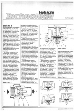
Atmospheric air always contains a certain amount of water vapour and as this water accumulates in the reservoir provision must be made to drain it away. Drain cocks are fitted for this purpose and in some cases they act automatically. Bendix supplies the type illustrated in Figures 2 and 3 which are reproduced by permission of that company. Referring to Figure 2,
the device consists of an
aluminium alloy body "A" with a cover "B" at the bottom. "C" is a rubber diaphram which is retained in a nylon guide "0".
The lower part of the diaphram forms the exhaust valve "E" which closes on seat "F", "G" is the condensate outlet. The upper part of "C" forms the inlet valve "K" which closes on seat "L". The unit is screwed into the reservoir by the screwed adaptor "M".
When there is no air pressure in the reservoir the exhaust valve portion "E" and the inlet portion "K" of the diaphram "C" are seated at "F" and "L" respectively. See Figure 3(a). When air pressure begins to rise the inlet valve "K" opens allowing the expulsion of condensate from the reservoir into the sump "J". Figure 3(b). The inlet valve remains open while the air pressure rises. When the maximum pressure is reached the pressures on each side of the diaphram "C" balance and the inlet valve closes and the exhaust valves remain seated see Figure 3(c). drop in the pressure of about 0.14 bar, (2 psi), allows diaphram "C" to be lifted momentarily because of the superior pressure in sump "J" Exhaust valve "E" is lifted off i seat allowing the pressure in t sump "J" to expel the condensate through the outlet "G". See Figure 3(d). The reservoir may be manually drained by lifting the stem "H' which will lift the valve "E" off its seat.
Below: Figure 3.