


Increasing Turbulence in Petrol Engines
Page 42
If you've noticed an error in this article please click here to report it so we can fix it.
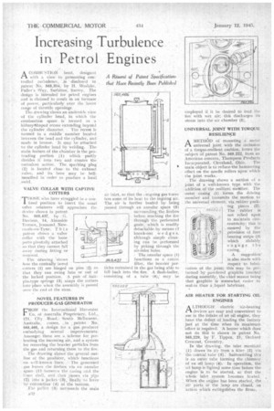
ACOMB! !STIoN head, desigucal ith a view to promoting controlled .1 turbulence, is .disclosed in patent • No. 565,394, by H. Weslake, Fuller's •Way, Surbiton. Surrey. The design is intended for petrol engines and is claimed to result in an increase of power, particularly over the lower range of throttle openings. Thu drawing shows an underside view cif the cylinder head, in which the combustion space is totmed as a kidney-thaped recess extending beyond the cylinder. diameter.. The recess is Formed in a middle' member located between the head and the cylinder, and made in bronze. • It may be attached to the cylinder head by welding. The main feature, of the charnber Is the protruding portion (1) which partly divides • it into two and creates the turbulent action, The sparking plug (2) is located close to the exhaust valve, and its bore may he bah: mouthed order to ptoduee a local
VALVE COLLAR WITH CAPTIVE COTTERS
10SE who have struggled in a con/ tined position to insert the usual valve retainers will appreciate the . device shown in patent . No. 565,437, by G. Davison, 14, Akenside Terrace, Jcsmond, NeWcastle-on-Tyne. 'I' i s . patent shows a valve collar with the loose parts pivotally attached so that they cannot fall away (luring fitting or removal . The drawing 'shows how the conically bored cotters (1) are binged on pinsso that they can swing into or out of " the locked position. A pair of hairpin-type springs 13).. snaps the critters into place when the assembly is passed. over the end of the stem.
NOVEL FEATURES IN PRODUCER-GAS GENERATOR
pROM the International [harvester Co. of Australia Proprietary, Ltd., 171, City Road,South Melbourne,
Australia, empea. patent
565,466, a .design Aar a gas producer embodying several im.provements. Amongstthese are a. scheme for preheating the•incorniug air, and a system for removing the heavier particles from the gas and returning them to the lire. The drawing shows the general outline of the producer, which functions on aell-known The generated gas leaves the firebox via au annular space 01 • lietwevn the caaing iind the jailer shell, and then' passes via pipe -(2) into a jacket -(.1)-, finally •Tfi leave by connection (4) at the bottom. The jacket (3) aur.ronnds the aniin
• aa2
air inlet, so that the ongoing gas trariafers some of its heat to the ingoing air. The air is further heated by being passed through an annular space (5) surrounding, the firebox before reaching the fire through the perforated grate, which is readily detachalara by means. cf knock-out wedge s. although simple c3eaning can be .performed by poking through the The annular space (1) functions as a coarae filter, the heavier particles entrained ill the gas being able to fall back into the, lire. A flash-boer, consisting of a lilac •(6); may he employed if it be desired to teed the lire with wet air;discharges its
h this discha h this discha
steam into the air camber (5). UNIVERSAL JOINT WITH TORQUE RESILIENCE A METH& Of mounting n metal ri universal joint with the inclusion of a torque-resilient cushion, forms the subject of patent No. 565,222, from an American concern, Thompson Products Incorporated, Cleveland, Ohio. The main object is to reduce—the hammering effect on the needle rollers upon which the joint works., -rhi drawing shows a section of a joint of a well-known type with the addition, of the resilient meMber. The outer casing (1) forms the driving member and transmits the motion to the universal element, vikrubber packing pieces (2). The rubber is not relied upon to maintain concentricity; this is assured by the .provision of four bearing strips (3) which slidably engage the easing, n -A •suggestiois also made with respect to lubriaction of the joint; this may be perarmed by powdered graphite inserted during assembly, the chief reason being that graphite is somewhat easier to seal-in than a ,liquid lubricant.
AIR HEATER FOR STARTING OIL ENGINES
.A LTHOUGH• electric air-heating 1-1 devices are easy andconvenient to use in the intake of an oil engine, they have the defect of loading the battery just at the time when its maximum 'effort is required. A heater which does not do thii is shown in patent No. 565,229, by F. Tippen, 21; Orchard Crescent, Coventry. In the drawing, the inlet manifold (1) draws 'its air from a, filter (2) via the.central tube (3). Surrounding 1.11:s is an outer tube forming the chimney of an oil lamp • (4). In operation, the oil lamp is lighted sometime before the engine •is to he started, so that the whole inlet system becomes heated. -When the engine has been started, -the air r° of of the lamp are closed, an action which extinguishes the flame. •