


Bonded Rubber-to-Metal Couplings
Page 36
Page 37
Page 38
If you've noticed an error in this article please click here to report it so we can fix it.
for the suppression of torsional vibration
By
F. Sumner) .
A.E.
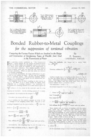
IN a previous article, published in " The Commercial Motor " dated August 18, the design of rubber-to-metal units, for linear loads was discussed, and it was shown now these utits could be applied to the _suppression of shock and linear vibration. In a similar manner, bonded rubber-to-metal units can be used for the reduction of torsional vibration. When so used the units are referred
to as flexible couplings. . As previously mentioned, for large deflections it is preferable to use rubber in shear.. In the case of couplings,
this is torsidnal shear. The previous -modulus figures quoted will, therefore, hold good for all calculations perlaining to tcrtonal shear. The simplest 'arm of shear coupling 'is that shown in Flo.Y. 1. In effect, it is a short length of rubber shaft subjected to a twisting moment. In textbooks on mechanics the resisting moment of a 50E11 baft is given as I.3.133
-where 1, is the stress in the material. and D is the 16 diameter of the .shaft. As the twisting moment T = resisting moment . the formula for the torque I ' Let 1i radians be the -relative amount of twist of the two flanges of the coupling under load. 7 The arc a sub
tending 6 measured. on the ,eurve surface =_06 Now the
2 .•
Alternatively, the coupling, may be in the form Of a hot cl,,v %haft. as -111alogn in Fig. 2. Againe=:.-o-rA211
Another simple type of coupling is that shown in Fig. 1 Ill this the metal parts are shaped like the frustum of a cone. This shape maintains a constant stress on the bond between the rubber and the metal part when the two conical surfaces have a common vertex.
And stiffness K..f:1--G7mrir+r) torque units per sadian.
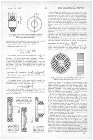
Nlarty readers will, no doubt, be' lamiliar with the rubber bush which has been applied with success to many engineering problems. The writer has seen types of this bush used as couplings on many occasions and deflections up io 270 degrees have heel, registered without failure'in the rubber, or bond between the rubber and the metal flanges. Such a bush is shown in Fig. 4.
For constant stresSin the bond, the inner metal part will, obviously, be longer than the outer part, as the bond area of the outer member is 2aRf, and that of the inner member ErrI„ it follows that the length of the inner member L will be —Rf
is the Maximum torque is that which is capable of being
transmitted by the bond on the inner member, it is assumed that the limiting stress is occasioned at this point. Area of bond on inner member A = 2rrL.
constant. This is the equation for a parabola. Therefore, the rubber component must be of parabolic form.
Shear strain is defined as the angle of shear. When the deflection is small, this angle is approximately the same as its tangent. For small deflections it can be proved by elementary calculus that the deflection 0 in radians is the easily be found from K =— The formulae given for the bush-type of coupling are only applicable for small deflections. Where a coupling of this type is used for large deflections, then The torque T is similar to the formula for a bush for small deflections and can be found from T = 2=1..LL, In all calculations the stress t should not exceed 50 lb. per sq. in. of 1:Kind area. The couplings described are all ot the simple shear type. In order to increase the torque-carrying capacity of those couplings shown in Figs. 2 and 3, without increasing their diameters, it is necessary only to put an additional plate in the middle of the rubber, as shown in .Figs. 5 and 8. This has the effect of doubling the bond areas and consequently the torque-carrying capacity. With this arrangement it will be necessary to couple the outer members to the driven part, whilst the middle plate becomes the driving flange.
In order to allow for end movement along the axis, a combination of Figs. 2 and 4 is sometimes used, as shown in Fig. 7. This combination a:so permits of greater. angular deflections.
It will be obvious that the maximum torque will be that transmitted by the centre, bush, whilst the maximum deflection will be the added deflections of the-centre bush and the sandwich.
As the bush and sandwicn are in series, the stiffness of the whole Coupling will be found by adding the twoiprung Where it is necessary to transmit large torques with limited sizes of couplings, it is often necessary to use the rubber in compression. As previously stated, the deflec tion must be limited to 10 per cent, of the thickness of the rubber. Fig. 8 shows a compression type of coupling with wedges of rubber between the metal driving vanes. This type is highly satisfactory when used as a flexible drive for magnetos, dynamos. water pumps and other accessories. With an adjustable or vernier backplate, adjustment can easily be effected when necessary. There are several variations, but all are fundamentally the ,same.
In order to work out the maximum torque to be transmitted by the compression-type of coupling it is necessary to know the area ratio of the rubber wedge. This means that, first of all, a rough draft of the coupling will have to be made showing the permissible outside diameter, thickness and number of vanes in the coupling.
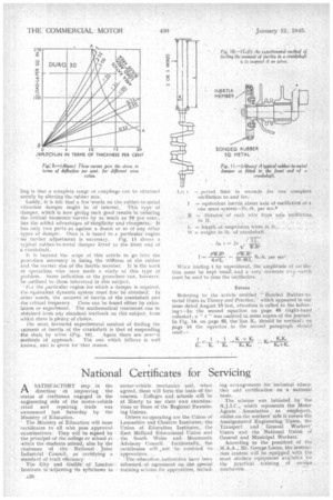
The permissible.stress can be obtained from a series of curves similar to those by Walter C. Keys, in his paper on "Rubber Springs," presented before the American Society of Mechanical Engineers in New York, in December, 1936. These curves give the stress in terms of deflection per cent, for different area ratios. A reproduction of one of these curves is shown in Fig. 9 and is representative of a rubber mix of 30 Durometer hardness.
Reading upwards from 10 per cent, we strike a curve which corresponds to the particular value of the area ratio we require. From this point, horizontally, can be seen the. permissible stress in lb. per sq. in. of load area. Load per vane stress x by area of vane. Then the total load . will be the number of vanes multiplied by the load on one vane. The total torque will be the total load on all vanes divided by the mean effective radius of the vanes.
Should the torque prove inadequate, a harder rubber must 'be tried by reference to the appropriate chart. Alternatively, more vanes must be incorporated in the design where possible. One great advantage of the rubber-to-metal coup
ling is that, a complete range ol couplings can be obtained merely by altering the rubber mix.
Lastly, it is felt that a few Words on the rubber-to-metal vibration damper might be Of interest. This type of damper, which is now giving such good results in reducing the Critical hernionit'curves by as much as' 70 per cent., has the added advantages of aimplicityand -cheapness:. It has only two parts as against a dozen or So of any other types of damper. Once it is tuned to a particular engine -no further adjustment is necessary. Fig. 11 shows a typical rubber-to-metal damper fitted to the front end of -a crankshaft.
It is beyond. the .cope of this article to go into the procedure necessary in fixing the stiffness of the rubber and the cot reel size of the inertia member. It is the work of specialists who nave made a study of this type of problem. Some indication of the procedure can, however, be outlined to those interested in this subject.
For the particular engine for which a 'dampei is required, the equivalent dynamic system must first be obtained'. In other words, the moment of inertia of the crankshaft and the critical frequency. nese can be found either by calculation or experiment. ' The mathematical treatment can be obtained from any standard textbook on this subject, from which there is plenty of choice.
The most favoured experimental method of finding the -moment of inertia of the crankshaft is that of suspending
the shalt by wires .(Fig. 10). Again there are seve-al methods Of approach. The one which follows is well known, and is given forAhat reason. When finding t by experiment, the amplitude of oscillation must be kept small..and a very accurate st(a-wetch must be used to time the 'oscillation.
Referring to the article entitled " Bonded Rubber-tometal Units in. Theory and Practice," which appeared in our issue dated August 18 last, attention is called to the followiug t---In the second equation on page 48 (right-hand column), a " t" was omitted in some copies of the journal. In Fig. 14, on page 49„ the line K, should be vertical; on page 50 the equation in the second paragraph should read:—