


Patents Completed.
Page 20
If you've noticed an error in this article please click here to report it so we can fix it.
FRICTIONCLUICH.—Albion Motor Car Co., Ltd., and Another.—No. 17,511, dated 23rd July, 1910.—In this invention there is described a single-disc friction clutch in which annular friction surfaces are used. A flanged disc is attached to the driving shaft, and has attached to it a steel ring, to which is fixed one friction surface ; a eecond dished disc is arranged outside, guided by bolts fixed in the flywheel, and carrying a second friction surface. The driven shaft has a spherical bearing formed on one end, engaging a similar bearing on the other shaft. The outside member of the spherical bearing engages with a toothed ring, to which is attached a flat friction disc. This is situated between the two friction surfaces already mentioned. This clutch was briefly described in our issue for 1st September, 1910.
MUDGUARDS. — Nichols. — No. 29,587/1909.—Cognate Application, No. 13.378/1910, dated 17th December, 1909 --This invention relates to mudguards for wheels of motor or other vehicles and is of the type fitted to elle side of the wheels for intercepting the lateral mudsplashing. A flap of leather, or of canvas or other suitable material is suspended lay two pins working in a curved slot.
This slot is formed in a plate banging from a ring supported in roller bearings on another ring suitably attached to the hub of the wheel, The inner ring is attached to and adjusted by radial stretchers. The curved slot is arranged eccentrically with regard to the wheel and is BO adjusted that the mudguard when it swings. through striking a stone or other obstacle, always swings within the circumference of the wheel, inetead
of projecting therefrom. Suitable weights or springs are provided to keep the mudguard normally in a vertical position.
INTERNAL COMBUSTION ENGINES.--Woiseley Tool and Motor-car Co., Ltd., and Remington.—No. 28,673, dated 8th December, 1909, and Cognate Application No. 6,311, 1910.—The distinctive feature of this invention is the utilization of one or more of the cylinders of a multi-cylinder internal-combustion engine as a pump for the supply of air to any of the cylinders and of the other pistons as pumps for the supply of mixture as required. The distribution of the air and mixture may be through a single rotating valve divided into two concentric chambers for the air and mixture respectively, or by poppet valves, or by any other convenient type. The lower part of each of the cylinders is closed by a sleeve, through which the piston rod, suitably packed, passes. This sleeve forms a guide for the cross-head. Ports are provided iii the cylinder, for the air inlet to the underside of the piston, for the exhaust from the upper side and one fur the supply of the scavenging air and mixture from the distribution valve. Instead of closing the lower ends of the cylinders, they may be left open and the crankcase may be divided into compact merits, each one of which forms a pump chamber for the corresponding cylinder. Another development of the invention provides, in connection with each cylinder, instead of an exhaust port which opened by the piston at the end of the downward stroke, a mechanically-operated exhaust valve which opens once only during the engine cycle, i.e., towards the end of the firing stroke. Then the scavenging air. which, supplied by another of the cylinders acting as a pomp. is forced into the cylinder, is compressed on the upward stroke of the piston. and none is allowed to escape. When the mixture is forced in. the pressure in the cylinder is considerably increased, and a more-powerful combustible mixture is obtained than when the exhaust is controlled simply by the piston. Another construction is one in which the piston is formed of two diameters, the larger one being the lower. The air or mixture. as the ease may be, is drawn in and compressed in the annular space above the largo portion of the piston surrounding the smaller portion. The various types are illustrated, together with various forms of valve.
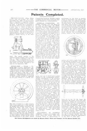
ATTACHMENT OF STEERING IVHEELS.—Crossley and Another.—No. 19.741. dated 24th Aueust, 1910.—This invent km relates to improvements in
attachments for the front or steering wheels of automobile road vehicles, and it consists: first, of a method of placing the axle swivel-pin in front of the steering-wheel centre, in the vertical plane of such wheel, and at such an angle to the vertical centre line of the wheel that the centre line of the swivel-pin, if produced, will intersect the vertical centre line of the wheel at the point of contact with the ground; secondly, it consists of a means whereby the swivelling-hub is directly linked to the transverse con
'meting rod which couples both wheels of the steering mechanism ; and thirdly iii such an arrangement of the parts as will permit the use of a detachable
wheel. The axle is formed with the usual jaw-shaped ends in which the swivel-pin or sleeve is arranged free to rotate in the usual manner and to which is secured the bearing housing and brake-shoe anchorage disc. The brake drum is mounted on the hearing pin, which forms the inner member of the bail bearings contained in the usual housing. According to this construction, it is stated that the following advantages are obtained. First, it is possible to position the link of the transverse steering rod accurately without resorting to a brake drum of excessive diameter. This is of special advantage when long wheel
bases are in use, for the longer the wheel-base. the greater will be the angle obtained by joining the swivel-pins to the rear axle, and, as a consequence, if the ordinary arrangement of steering pivot be used, the link pin would be proportionately further from the wheel centre and would necessitate the use of e brake drum of large dimensions, because the internal diameter of the drum has to clear this pin. Secondly, the link or joint of the transverse steering rod is formed directly upon the swivelling-hob without the inter-position of any lever or extra part.