


Know Your Air Brakes
Page 35
If you've noticed an error in this article please click here to report it so we can fix it.
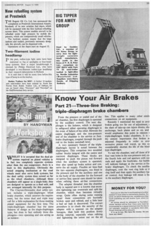
Part 21—Three-line Braking: triple-diaphragm brake chambers
From the pressure or sealed end of the air chamber, the first diaphragm is operated by the auxiliary control. The next diaphragm is the isolator, which is designed to safeguard either operating diaphragm in the event of failure of the other. Between the centre diaphragm and the non-pressure end of the chamber is the service or footbrake diaphragm, coupled through the push rod to the brake camshaft lever.
A very necessary feature of the triplediaphragm layout is noted between the diaphragms. This comprises two moulded rubber blocks integral with the centre and rearmost diaphragm. These blocks are designed to push the piston rod forward when the auxiliary system is operated; they also speed up brake action and conserve the air supply. Flexible air lines feed the two separate diaphragms, one fitted in the pressure end for the auxiliary and one in the body of the chamber for the forward or service line; special care should be taken when refitting these air-line connections.
The adapter threaded into the chamber body is tapered and it is known that excessive tightening can overstrain and split the chamber, which then becomes virtually scrap. Quite often during some running repair these connections are hurriedly broken open and refitted, and a little later a bad air leak is discovered. The correct procedure is to check the security of the adapter with a spanner on the adapter hexagon, then hold this position firmly during removal, especially when refitting and tightening the union nut on the air line. This applies to many other simik connections on air equipment.
Recently I mentioned the need to avoi brakes going too far out of adjustment, z the slam of take-up can injure drums, sho anchorage, back plates and so on, and would emphasize this point in relation t triple-diaphragm brake chambers. It is ( the utmost importance that brakes at adjusted frequently in order to avoi excessive piston rod travel, as this ca considerably shorten the life of the blocl type diaphragm.
To test the chamber, seal off three of -El four vent holes in the non-pressure end, co; the fourth hole and rod aperture with SO2 suds and apply the footbrake. Air bubbl, will indicate leakage at the service or foc brake diaphragm. To check the auxiliai diaphragm, coat the vent ring hole or tl ring itself and then apply the auxiliary hat air control. Any leakage will mean a fat in the auxiliary diaphragm.