


Self-adjusting Steering
Page 72
If you've noticed an error in this article please click here to report it so we can fix it.
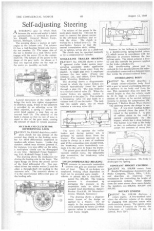
ASTEERING gear in which slack between the worm and sector is taken up automatically, is covered by patent No. 836,682. (General Motors Corp., Detroit, Michigan, U.S.A.)
The drawing shows a section at rightangles to the column axis. The column ( I) has a ball-bearing thread and moves the nut member (2). The upper side of the nut is formed as a rack whose teeth _engage with the sector (3) on the rockershaft (4). The subject of the patent is the shape of the gear teeth. As shown at 5 they are tapered either on the rack or the sector or, possibly, on both.
Lateral movement of the rocker-shWft brings the teeth into tighter engagement to eliminate slack. Force in this direction is provided by an adjusting screw (6). Once adjusted, a spring (7) presses the screw head against a stop face on an inserted bush (8). The material of the bush is chosen so that its i.ate of wear is equal to that of the gear teeth, causing the amount of slack to remain constant.
MULTI-PLATE CLUTCH FOR .
DIFFERENTIAL -LOCK PATENT No. 836,662 describes a multiplate clutch for use instead of the normal dog clutch as the locking member for third differentials employed in tandem-axle driven bogies. Unlike dog clutches, which may become. jammed if, for instance, tyre sizes differ on the axles, a. multi-plate clutch can be disengaged at any time. (Kirkstall Forge Engineering, Ltd., Kirkstall Forge, Leeds, 5.)
The drawing shows the mechanism for driving the leading axle in the bogie. The input flange (1) drives the planet carrier of the third differential (2). One sunwheel drives the tubular worm (3) and the other a through-shaft (4) leading to the rearmost axle. The assembly shown at 5 is the conventional differential gear of the leading axle. The subject of the patent is the multi-plate clutch (6). This can be used to connect the planet carrier to the left-hand sunwheel and so lock the drive. The clutch is worked by a forked lever (7). An unorthodox feature is that the central transmission shaft, sliding on its splines, serves also as a push-rod.
The clutch may be operated manually or by a compressed-air cylinder.
SINGLE-LINE TRAILER BRAKING
PATENT No. 836,200 shows a servo operated trailer brake system incorporating automatic brake application should the trailer break away from the tractor. •A single pipe only is employed between the two units. (Feeny and Johnson, Ltd., and others, 134-6 Ealing Road, Wembley, Middlesex.)
The drawing shows a diagrammatic layout in which the tractor brakes are • Worked hydraulically from' the pedal • through a pipe (1). The pipe branches to a suction control valve (2). When the tractor brakes are applied, suction is transmitted to the pipe (3). This includes a breakaway valve (4) and leads to a vacuum tank (5) on the trailer. The tank has two supply pipes, one of which contains a one-way valve (6).
The servo (7) operates the trailer brakes and, during normal use, is powered by suction direct from the tractor. The vacuum reservoir on the trailer is always in a state of readiness and, if the connecting pipe should break, the breakaway valve immediately connects it to the servo to brake the trailer.
The patent gives detail drawings of the vacuum control valve, the detachable pipe connection, the breakaway Valve and the servo.
LOAD-COMPENSATED BRAKING
THE pressure in pneumatic suspension systems can give an accuraIe indication of load. Thus, if air-brakes are employed, braking effect dependent on
load can be provided quite simply. A scheme to permit this is described in patent No. 836,160. The braking pressure is determined by averaging the pressure in the suspension units to allow for unequal load distribution. (ICnoirBremse G.m.b.H.. 80 Moosacherstrasse, Munich, Germany.) The drawing shows a diagrammatic layout of the design as applied to a trailer. The air supply to the suspension bellows (1) is controlled by levers (2) which operate valves to maintain a constant frame height. Pressure in the bellows is transmitted to a double-acting spring-loaded piston (3) which moves in accordance with the difference in pressure between the two bellows units. The piston actuates a lever (4) and this controls the pressure applied to the brake cylinders (5).
The double-acting, piston canbe replaced by two parallel pistons (in separate cylinders) connected to a balance beam that works the pressure-control lever.
OVERLOADING BODY PATENT No. 837,021 describes a I simple refuse-collection body fitted with a gear to permitaverIciading through an aperture in the body roof from the rear. This equipment does nOt limit the overall height so that the vehicle could be 14 ft. high to allow a satisfactory amount of refuse to be carried without recourse to devices for compression. (W. Thurgood, 7 Walton Road, Ware, Herts.) The drawing shows the design in out line. A low-level loading hopper (I). pivoted about the point 2, is raised to the position 3. A pair of rubber doors in the roof is opened automatically by the hopper, which has a drop bottom. The hopper is as wide as the body so that, on collection work, it can accept the contents of many bins between loading operations. The body is discharged by tipping.
CONSTANT HEIGHT CONTROL
DATENT No. 838,808 comes from
Bendix-Westinghouse Automotive Air Brake Company, Elyria, Ohio, U.S.A., and describes an improved valve mechanism for controlling the height of air-suspension systems. Other patents from the same source show more details; the numbers are 838,810, 839.099 and 839,103.
ROTARY ENGINE
PATENT No. 838,166 discloses a rotary engine. A two-toothed rotor alters the effective volume of its casing by engaging with adjacent rotors with tooth-receiving spaces. The patent comes from Institut Francaise du Petrole, des Carburants et Lubriflants, 2 rue de Lubeck, Paris XVI.