


Forced-air Cooling for Brakes T HE increasing speeds and weights of
Page 66
If you've noticed an error in this article please click here to report it so we can fix it.
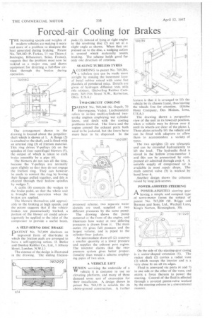
modern vehicles are making it more and more of a problem to dissipate thc heat generated during braking. Patent No. 769,182 (P. Farkas, 11 rue Thiers Boulogne, Billancourt, Seine, France), suggests that the problem must now be tackled as a major one, and shows equipment for directing a full-flow airblast through the 'brakes during operation.
The arrangement shown in the drawing is located about the propellershaft which is shown at 1. A flange (2) is attached to the shaft, and is fitted with an internal ring (3) of friction material. This ring drives V-pulleys (4) on the spindles of four centrifugal blowers (5), the output of which is taken to each brake assembly by a pipe (6).
The blowers do not run all the time, because the V-pulleys are normally open slightly so that they do not engage the friction ring. They can however , be made to contact the ring by having their flanges pulled together, and this is effected through their hollow spindles by wedges 7.
A cable (8) connects the wedges to the brake pedal, so that the whole unit is brought into operation when the brakes are applied.
The blowers themselves add appreciably to the braking at high speeds, and the patent suggests that if the vehicle brakes are pneumatically worked, a portion of the blower air could advantageously be applied to the inlet of the compressor to provide a useful boost.
A SELF-SERVO DISC BRAKE DATENT No. 767,099 discloses an
improved form of disc-brake in which the friction pads are arranged to have a self-applying action. (J. Butler and Dunlop Rubber Co., Ltd., 1 Albany Street, London, N.W.1.) The essence of the design is illustrated in the drawing. The sliding friction
pads (I), instead of lying at right angles to the revolving disc (2) are set at a slight angle as shown. When they are pressed on to the disc, a wedging action is created which materially assists braking. The scheme holds good for only one direction of rotation.
SEALING TUBELESS TYRES
ACCORDING to patent No. 769.286,
a tubeless tyre can be made more airtight by making the innermost layer of butyl rubber mixed with some fine platelets of powdered mica. Details are given of hydrogen diffusion tests with this mixture. (Sieberling Rubber Company, 345-15th Street NW., Barberton. Ohio. U.S.A.) 1WO-CIRCUIT COOLING
DATENT No. 769,168 (G. Ospelt, 70
Herrengasse, Vaduz, Liechtenstein) refers to in-line multi-cylindered twostroke engines employing wet cylinder liners, and deals with the cooling problems involved. The liners and the region around the exhaust ports both need to hc jacketed, but the liners have more heat to be dispersed. In the proposed scheme, two separate wale circuits are used, supplied at two different pressures by the same pump.
The drawing shows the pump mounted at the front of the engine, and illustrates how water at two differing pressures is drawn from it. The main outlet (1) gives full pressure and the largest volume, and is piped to the cylinder-liner jackets.
An intermediate draw-off (2) removes a smaller quantity at a lower pressure and supplies the exhaust port region. The inventor claims that the twopressure system gives better proportionality than would a scheme employing pipes of two sizes, A VEHICLE LIFT
WHEN servicing the underside of a vehicle it is common to use an elevating platform, and many of these demand some sort of excavation for their installation. A design shown in patent No. 769,135 is notable for its above-ground construction. A further
feature is that it is arranged to lift the vehicle by its chassis frame, thus leaving the wheels free for attention. (Globe Hoist Company, Des Moines, Iowa, U.S.A.)
The drawing shows a perspective view of the unit in its lowered position, when a vehicle may be driven over it until its wheels are clear of the plates 1. These plates actually lift the vehicle and can be fitted with adaptors to allow them to accommodate a variety of types.
The two uprights (2) are telescopic and can be extended hydraulically to lift the load. The hydraulic fluid is stored in the hollow cross-member 3 and this can be pressurized by compressed air admitted through cock 4. A suitable supply of compressed air is available in most repair shops. The math control valve (5) is worked by hand lever 6.
Another design shows the columns raised by long jack-screws.
POWER-ASSISTED STEERING
A POWER-ASSISTED steering gear n. having a simple and compact type of servo-motor forms the subject of patent No. 767,208 (W. Briggs and Burman and Sons, Ltd., Wychall Lane, King's Norton, Birmingham, 30),
On the side of the steering-gear casing is a sector-shaped extension (1). The rocker shaft (2) carries a radial vane (3) which sweeps the interior and is a very close fit on all its edges.
Fluid is conveyed via ports (4 and 5) to one side or the other of the vane, and exerts a force thereon to power the steering. Control of the fluid is effected through a co-axial piston-valve worked by the steering column in a conventional manner.