


COMMERCIAL MOTOR BODY IMPROVEMENTS.
Page 32
If you've noticed an error in this article please click here to report it so we can fix it.
A Résumé of Recently Published Patents
In specification No. 159,303, by Percy Frost Smith and others, of TillingStevens Motors, Ltd., of Maidstone, the patentees refer to the difficulty of loading or unloading totally enclosed bodies, particularly when sach loading is most conveniently to be effected by means of a crane or hoist. They have, therefore, devised One, means of reducing this difficulty. It takes the form of a sliding cover to the roof of the vehicle.
A rectangular gap is formed in the roof, starting from the rear end, and extending for a distance somewhat less than half of the length of the body. A sliding roof is designed to cover this gap, and near both longitudinaledges of this sliding portion are arranged rollers mounted on spindles bearing in a, metal plate embodied in the sliding roof. The gap in the main roof is reinforced by a metal-bound wooden flange, and this flange is prolonged in the form of a strip or rail throughout the length of the main roof.On the upper surfaces. of these strips are fixed inverted channels of such width that the rollers in the sliding roof are a loose running fit in the grooves of the. channels. The edge of the sliding roof is also reinforced by means of a metallic channel plate, and this is cceitinued below the edge of the roof, and splayed outward so as to Lorin a projection for the purpose of preventing the entry of rain, which might easily be driven inwards and upwards by the wind, and thus get beneath the main roof. As a further prevention against water lodging in the mechanism, and particularly in the channel along which the rails run, drain holes are Silted at intervals, leading from the channel through the reinforcing strip and out on to the main roof.
OtherTatents of Interest.
Most people,are by4now familiar with impulse starters for magnetos.. For the benefit of those who have not yet come in contact with this special type of ignition fitting, we may point out that it is an attachment designed temporarily to restrain the magneto armature while the engine is being revolved slowly by hand, only releasing it at the preeise moment when a spark is required m any cylinder. When released, the armature, acting under the influence of a spring, which has been wound weile the, armature has remained stationary, flips round at high speed, and thus produces the necessary current for a. good spark. As a. rule, this impulse starter is mounted on the B36
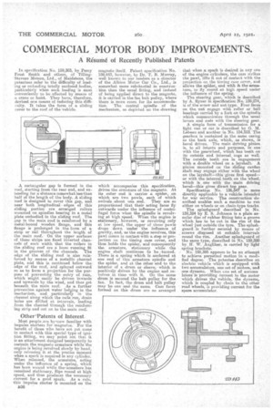
magneto itself. Patent specification, No. 159,443, howeVer, by Dr. T. B. lgurray, well known to our readers as a director of the Albion Motor Gar Co., Ltd., is somewhat more substantial in construction than the usual fitting, and instead of being applied direct to the magneto, it is curried in the fan belt pulley, where there is more room for its accommodation. The central spindle of the mechanism, as depicted an the drawing
which accompanies this speeificafon, drives the armature of the magneto. At its outer end it carries a spider, on which are two pawls, each a which swivels .about one end. They are so proportioned that their acting faces fly outwards under the influence of centriJugal foroo when the spindle is revolving at high speed. When the engine is stationary, however, or revolving only at low speed, the upper of these pawls drops down under the influence of gravity, and, as the engine revolves, this pawl comes in contact with a step or projection on the timing case cover, and thus holds the spider, and consequently the armature, stationary while the engine shaft continues to be -turned. There is a spring which is anchored at one end of this armature spindle and the spider, and at the other end to the interior of a drum or sleeve, which is positively driven by the engine and revolves in time with it. On the same drum is secured the belt pulley for the fan. In fact, the drum and belt pulley may be one and the same. Cam faces formed on this drum are so arranged that when a spark is desired in any one of, the engine cylinders, the cam strikes the pawl, lifts it out of contact with the projection on the timing case cover, arid allows the spider, said with it the armature, to fly round at high speed under the influence of the spring. The steering gear, which is described by A. Ryner in specification No. 159,274, is of the screw and nut type. Four faces on the; nut engage with roller or ball bearings Carried by a fork on the spindle which communicates through the usual levers and rods with the steering gear.
A simple form of transmission for a light van or earls described by G. M, Lehea,u amid another in No. 154,553. The gearbox is contained in the Same easing as the back axle' which, as shown, is bevel driven. The main driving .pinion is, to all intents and purposes, in one with the gearwheel, which has teeth on its outside and iinternal:cogs as well. The outside teeth are in engagement, with a double wheel on a layshaft. A pinion mounted on the sliding ca.rdan shaft may engage either with the wheel on the layshaft—this gives first speeder with the internal teeth_ on the wheel, whie.h is one with the main driving bevel—this gives direct top gear.
Specification No. 136,547 is more directly applicable to a vehicle intended for war service. The construction described enables such a machine to run either on wheels or on chain-type tracks The splashguard described in No, 159,324 by E. S. Johnson is a plain an nular disc of rubber fitting into a groove Which has to be cut in the rim of the wheel just outside the tyre. The splashguard is further secured by means of screws disposed at suitable intervals round the rim. Another splashguard of the same type, described in No. 159,320 by IL W. Angliker, ie carried by light spring brackets.
No. 159,595 appea-rs to be an attempt to achieve perpetual motion in a modified degree. The patentee describes an
electric vehicle which is equipped with two accumulators, one set of motors, and one dynamo. When ene-set, of accumu labore is providing it•'.urrent to the motor which drives the vehicle, • the dynanio, which is coupled by chain to the other road wheels, is providing current for the spare accumulator.