


The Jackson Resilient Wheel.
Page 21
If you've noticed an error in this article please click here to report it so we can fix it.
Much inventive ingenuity has been expended upon the designing of some device to nullify the shocks which are inseparable from a heavy vehicle when travelling over ordinary road surfaces. ikt present the reduction ot undue vibration is confined to the springing, and the employment .of some make of rubber tires, of which there are a number of forms on the market ; some of these have a greater resiliency than the others, according to their section. In most instances, inventors have turned their attention to the production of a spring wheel, which, while it would act as an efficient shock absorber, would also be simple in construction, and economical under actual service conditions. Most of the wheels, unfortunately, for which, up to the present, Letters Patent have been granted, are too complicated in their designs for adoption by owners of self-propelled vehicles. Motor omnibus engineers would be perfectly willing to adopt a spring wheel if one could be found that would embody resiliency and economy of upkeep, always supposing that it did not materially add to the weight of the vehicle to which it was fitted. The question is a -difficult one to solve, because, sooner or later, the springs or rubber cushions, which are used as the medium to separate the rigid member of the wheel attached to the axle from that portion which carries the tread, must collapse. The replacements can be effected in some cases at a slight cost, and with little labour, by an ordinary yard hand who is able to use a spanner, but, generally speaking, spring wheels are too complicated for anyone, except those who are thoroughly conversant with their internal mechanism, to
repair without the services of an experienced man. Then, again, the writer is of the opinion that, in turning a corner, a motorbus would tend to sway outwards, owing to the compression of the springs or rubber cushions on that side. This, of course, in practice, might not be very noticeable, but the tendency would still remain, and, with the unnecessary camber on some roads, cause an extra side strain on the joints of the body work, or an increased risk of accident.
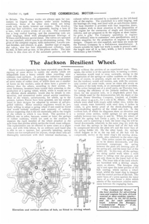
The writer formed one of a small party, on Thursday last, for testing the efficiency of the Jackson resilient hub, as fitted, for the occasion only, to a single-deck petrol bus. The vehicle used for the demonstration left the depot of the I.ondon Power Omnibus Company, Limited, at Cricklewood, about 12.45 p.m., for a run to St. Albans. The front wheels were shod with single solid rubber tires, whilst the back wheels were furnished with steel tires, 6 inches in width, to give better proof of the shock-absorbing and noise-deadening qualities of the wheel and hub. In the resilient hub, of which the diagrams show an elevation and a vertical cross section, coiled springs (a) are arranged radially between two rings (c and b). When the wheel, of which the spring hub forms a part, is rolling over the ground, and is sustaining a load, the inner ring (b) will be forced downwards, relatively to the outer ring (c), with the result that the springs in the lower half of the hub will be compressed between the plate (el) and the inner face of the spring holder (d). On the other hand, the springs which happen to be at the top half of the hub will be compressed, owing to the inner ring's (b) moving downwards, also, relatively to the outer ring (c). This action causes the spring pin (e) to be drawn downwards, and this movement compresses the spring between the plate (0) forming part of the spring pin, and the inner face of the holder (d). In this way, all the springs are doing useful work when a road wheel is rolling over the ground, and not only those on the lower half of the hub. The inner side of the back wheels are furnished with a driving attachment, as shown. The hexagon ring (q) is cast upon the outer portion of the hub casting, which carries a wheel tread, whilst the inner ring is integral with the central portion of the hub. Theouter faces of r press against the inner faces of q; this forms a drive which admits of the maximum relative movement between the engaging faces.
72