 1
1 2
2 3
3 4
4 5
5 6
6 7
7 8
8 9
9 10
10 11
11 12
12 13
13 14
14 15
15 16
16 17
17 18
18 19
19 20
20 21
21 22
22 23
23 24
24 25
25 26
26 27
27 28
28 29
29 30
30 31
31 32
32 33
33 34
34 35
35 36
36 37
37 38
38 39
39 40
40 41
41 42
42 43
43 44
44 45
45 46
46 47
47 48
48 49
49 50
50 51
51 52
52 53
53 54
54 55
55 56
56 57
57 58
58 59
59 60
60 61
61 62
62 63
63 64
64 65
65 66
66 67
67 68
68 69
69 70
70 71
71 72
72 73
73 74
74 75
75 76
76 77
77 78
78 79
79 80
80 81
81 82
82 83
83 84
84 85
85 86
86 87
87 88
88 89
89 90
90 91
91 92
92 93
93 94
94 95
95 96
96 97
97 98
98 99
99 100
100 101
101 102
102 103
103 104
104 105
105 106
106 107
107 108
108 109
109 110
110 111
111 112
112 113
113 114
114 115
115 116
116 117
117 118
118 119
119 120
120 121
121 122
122 123
123 124
124 125
125 126
126 127
127 128
128 129
129 130
130 131
131 132
132 133
133 134
134 135
135 136
136 137
137 138
138 139
139 140
140 141
141 142
142 143
143 144
144 145
145 146
146 147
147 148
148 149
149 150
150 151
151 152
152 153
153 154
154 155
155 156
156 157
157 158
158 159
159 160
160 161
161 162
162 163
163 164
164 165
165 166
166 167
167 168
168 169
169 170
170 171
171 172
172 173
173 174
174 175
175 176
176 177
177 178
178 179
179 180
180 181
181 182
182 183
183 184
184 185
185 186
186 187
187 188
188 189
189 190
190 191
191 192
192 193
193 194
194 195
195 196
196 197
197 198
198 199
199 200
200 201
201 202
202 203
203 204
204 205
205 206
206 207
207 208
208 209
209 210
210 211
211 212
212 213
213 214
214 215
215 216
216 217
217 218
218 219
219 220
220 221
221 222
222 223
223 224
224 225
225 226
226 227
227 228
228 229
229 230
230 231
231 232
232 233
233 234
234 235
235 236
236 237
237 238
238 239
239 240
240 241
241 242
242 243
243 244
244 245
245 246
246 247
247 248
248 249
249 250
250 251
251 252
252 253
253 254
254 255
255 256
256 257
257 258
258 259
259 260
260 261
261 262
262 263
263 264
264 265
265 266
266 267
267 268
268 269
269 270
270 271
271 272
272 273
273 274
274 275
275 276
276 277
277 278
278 279
279 280
280 281
281 282
282 283
283 284
284 285
285 286
286 287
287 288
288 A Built-up Connecting Rod
Page 206
If you've noticed an error in this article please click here to report it so we can fix it.
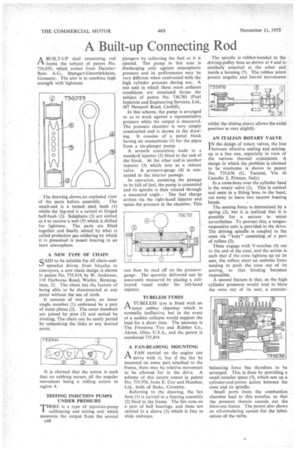
A BUILT-UP steel connecting rod 1"-1 forms the subject of patent No. 736,033, which comes from DaimlerBenz A.G:, Stuttgart-Untertiirkheim, Germany. The aim is to combine high strength with lightness.
The drawing shows an exploded view of the parts before assembly. The small-end is a turned steel bush (1) whilst the big-end is a turned or forged half-bush (2): Sideplates (3) are slotted at 4 to receive a web (5) which is drilled for lightness.. The parts are fitted together and finally united by what is called protective• gas soldering by which it is presumed is meant brazing in an inert atmosphere.
A NEW TYPE OF CHAIN
SAID to be suitable for all chain-andsprocket drives, from bicycles to conveyors, a new chain design is shown in patent No. 735,919, by W. Anderson, 118 Harborne Road, Warley, Birmingham, 32. The chain has the feature of being able to be disconnected at any point without the use of tools.
It consists of two parts, an inner single member (I) embraced by a pair of outer plates (2). The outer members are joined by pins (3) and united by riveting. The chain can be easily parted by unhooking the links at any desired point. • It is claimed that the action is such that no rubbing occurs, all the angular movement being a rolling action in region 4.
TESTING INJECTION PUMPS UNDER PRESSURE THERE is a type of injection-pump calibrating and testing unit which measures the output from the several c48
plungers by collecting the fuel as it is ejected. The pump in this case is discharging only against atmospheric pressure and its performance may be very different when confronted with the high cylinder pressure during use. A test unit in which these more arduous conditions are simulated forms the subject of patent No. 736,781 (Fuel Injection and Engineering Services, Ltd., 387 Newport Road, Cardiff).
In this scheme, the pump is arranged so as to work against a representative pressure while the output is measured. The pressure chamber is very simply constructed and is shown in the drawing. It consists of a metal block having six connections (1) for the pipes from a six-plunger pump.
A seventh connection leads to a standard injector (2) fitted to the end of the block. At the other end is another injector (3) which acts as a release valve. A pressure-gauge (4) is connected to the interior passage.
In operation, assuming the passage to be full of fuel, the pump is connected and its spindle is then rotated through a measured angle.. The fuel charge arrives via the right-band injector and raises the pressure in the chamber. This can then be read off on the pressure' gauge. The quantity delivered can be accurately measured by placing a calibrated vessel under the left-hand injector.
TuBEIRSS TYRES
A TUBELESS tyre is fitted with an r% inner rubber chamber which is normally ineffective, but in the event of a sudden collapse would support the load for a short time. The patentee is The Firestone Tire and Rubber Co., Akron, Ohio, U.S.A., and the patent is numbered 735,854.
A FAN-BEARING MOUNTING A FAN carried on the engine can move with it, but if the fan be mounted on some part attached to the frame, there may be relative movement to be allowed for in the drive. A scheme of this nature comes in patent No. 735,976, from E. Coy and Humber, Ltd., both of Stoke, Coventry.
Referring to the drawing, the fan boss (I) is carried in a bearing assembly (2) fixed to the frame. The fan runs on a pair of ball bearings, and these are carried in a sleeve (3) which is free to slide endways. The spindle is rubber-bonded to the driving-pulley boss as shown at 4 and is similarly attached at the other end inside a housing (5). The rubber joints permit angular and lateral movements whilst the sliding sleeve allows the axial position to vary slightly.
AN ITALIAN ROTARY VALVE TN the design of rotary valves; the line I between effective sealing and seizingup is a fine one, especially in view of the various thermal expansions. A design in which the problem is claimed to be overcome is shown in patent No. 735,636 (G. Tacconi, Via di Castello 2, Firenze, Italy), In a cross-bore over the cylinder head is the rotary valve (1). This is conical and seats in a fitting bore in the head, cut away to leave two narrow bearing bands.
The seating force is determined by a spring (2), but it is realized that it is possible for a seizure to occur nevertheless. To prevent this, a torqueresponsive unit is provided in the drive. The driving spindle is coupled to the cone via " keys" consisting of a pair of rollers (3).
These engage with V-notches (4) cut in the end of the cone, and the action is such that if the cone tightens up on its seat, the rollers exert an endwise force tending to push the cone out of its seating, so that binding becomes impossible.
A second feature is that, as the high cylinder pressures would tend to blow the cone out of its seat, a counter balancing force has therefore to be arranged. This is done by providing a small annular space (5), which sets up a cylinder-and-piston action between the cone and its spindle.
Small ports from the combustion chamber lead to this annulus, so that the pressure therein cancels out the blow-out forces. The patent also shows an oil-circulating system for the lubrication of the valve,