


Further Details of the Darracq Lorry.
Page 12
If you've noticed an error in this article please click here to report it so we can fix it.
We were enabled, in our last issue, to give first publication to some interesting advance particulars of the new heavy model which is now being constructed by the Darracq Co. It will be remembered that we reproduced three sectional drawings, of the engine, of the clutch, and of the back-axle worm drive respectively. We also intimated that further particulars of this company's latest design should be included in the present issue. We are now able to redeem that promise. We reproduce herewith two further constructional drawings of the complete chassis and of the change-speed gearbox respectively. Elsewhere in this issue (page 383) will be found two side illustrations of thc follt-cylinder engine. It will be noticed that the valve stems are enclosed by detachable aluminium
covers. The valve tappets are of eonsiderable diameter, but they are bored out and have large adjustable heads. Instead of placing the timing gears at the froet of the motor, Mr. C. R,. Garrard, who is now at the head of the Darracq technical department, has preferred to place them at the flywheel end of the case. A quieter and more-sweetlyrunning engine is claimed for this arrangement, and the compactness of the design allows the bonnet to be shortened; the timing gears and flywheel are disposed beneath the footboards.
The design of the pistons is interesting; the upper ring is really in duplicate. and actually consists of a deep outer ring, and behind it, carried one above the other, are a couple of rings, each of which is practically half the depth of the outer one. The second or lower ring is of the ordinary type. Immediately below the bottom ring the piston walls are cut away and are drilled with small hules, whilst the bottom of the piston is again of full diameter.
There are throe main crankshaft bearings, and these are contained in the upper portion of the chamber ; the lower part. of the latter acts only as an oil retainer. Lubrication is by pump through the drilled crankshaft. The oil flow is shut, off automatically when the motor is throttled down.
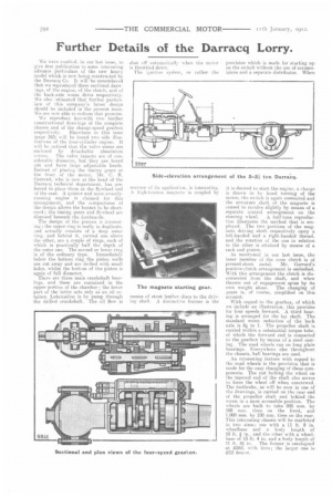
The ignition system, or rather the man»er of its applicatien. is interesting. high-tension magneto is coupled by provision which is made for starting up on the switch without the use of accumulators and a separate distributor. When it is desired to start the engine, a charge is drawn in by hand turning of the motor, the switch is again connected and the armature shaft of the magneto is caused to revolve slightly by means of a separate control arrangement on the
steering wheel. A half-tone reproduction illustrates the method that is employed. The two portions of the magneto driving shaft respectively carry a left-handed and a right-handed thread, and the rotation of the one in relation to the other is attained by means of a rack and
As mentioned in our last issue, the inner member of the cone clutch is of pressed-sheet metal. Mr. Garrard's positive-clutch arrangement is embodied. With this arrangement the clutch is disconnected from the shaft, and when thrown out of engagement spins by its own weight alone. The changing of gears is, of course, simplified on this account.
With regard to the gearbox, of which we include an illustration, this provides for four speeds forward. A third bearing is arranged for the lay shaft. The standard worm reduction of the back axle is 8i to 1. The propeller shaft is carried within a substantial torque tube, of which the forward end is connected to the gearbox by means of a steel casting. The road wheels run on long plain bearings. Everywhere else throughout the chassis, ball bearings are used.
An interesting feature with regard to the road wheels is the provision that is made for the easy changing of these components. The nut locking the wheel on the tapered end of the shaft also serves to force the wheel off when unscrewed. The footbrake, as will be seen in one of the drawings, is carried on the rear end of the propeller shaft and behind the worm in a most accessible position. The wheels are built to take 900 mm. by 100 mm. tires on the front, and 1,000 mm. by 10CI mm. tires on the rear. 'this interesting chassis will be marketed in two size,s ; came with a 11 ft. 8 in. wheelbase and a body length of 10 ft. in., and the other with a wheelbase of 13 ft. 4 in. and a body length of
11 ft. aq in. The former is catalogued at £565. with tires; the larger one is
12 dearer.