


A High-performance Two-stroke Engine
Page 52
If you've noticed an error in this article please click here to report it so we can fix it.
A Résumé of Recently Published Patent Specifications Obtainable from the Patent Office, Price is. each.
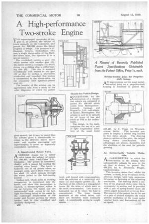
rr tIE supercharged two-stroke oil en
gine is, at present, the subject of much research on the Continent, and patent No. 5013,326 shows the latest progress in design. The patentee is G. Kammer, Geneva, Switzerland, who uses a single sleeve-valve of the BurtMcCollum type, but operates it in a special manner.
The crankshaft carries a gear (3) which meshes with another gear (1). The latter carries a crankpin (2) which drives, via a sliding shoe, a roller-bearing disc (5). This disc is mounted eccentrically with respect to the gear (1) so that its motion is alternately accelerated and retarded; this motion is transmitted to the sleeve-valve via the commonly used spherical-jointed stub (4): The benefits of the scheme can be appreciated only from a study of the valve diagrams, of which the patent gives several, but it may be stated that the scheme gives a considerable increase in the effective sleeve movement, and enables scavenging and supercharging to occur as separately controllable operations.
A Liquid-cooled Rotary Valve.
A' design for a rotary valve forms the subject of patent No, 506,967, from Auto-Union A.G., Chemnitz. The patent is concerned, chiefly, with a means for cooling the rotating valve barrel. The barrel is hollowed out at all points where no passages occur, and is fitted with a hollow shaft (1) which extends through the water jacket to the ball-bearing journal.
Sodium salt, which melts at working temperature, is introduced into the barrel, and _when this temperature is reached, a thermo-siphonic action is set up between the barrel and the water-cooled` neck, owing to the hot, light fluid being forced to the centre by the centrifugal displacement of the cooler and heavier portion by which further heat is then absorbed and similarly dissipated.
• a42 Chassis-less Vehicle Design.
CUGGESTIONS for the b-lconstruction of a chassisless vehicle arc contained in patent No. 498,897 which comes from MetropolitanCammell, Carriage and Wagon Co., Ltd., and others, of Saltley, Birmingham. The scheme is said to be suitable for all types of bus and coach as well as for trolleybuses.
The design, in the main, comprises the use of a pair of light longitudinal members at the usual frame
level, well braced with cross-members, with the addition of a waist-high stiffener (1) and angular girders (2). At . the front of the vehicle is a triangulated frame (s) the Sides of which meet at the front cross-member. This frame is laminated (as at 5) where the load is concentrated. The lower frames terminate at the wheel boxes, and these are therefore made unusually rigid. , A considerable saving in weight results, •
Rubber-bonded Joint for Propeller. shaft Casings.
AN improvement on the usual metalto-metal joint on a propeller-shaft housing is described in patent No.
507,497, by C. Voigt, 13, Woyrsch
strasse, Berlin, This inventor proposes to employ a rubber ring bonded
to two metal annuli. The drawing shows a section of the joint, the rubber being shown cross-hatched. The advantages are silence, durability and the abolition of the need for periodic greasing.
An Automatically Variable Choke. tube.
.1-A A CARBURETTER in which the
cross-section of the mixing tube automatically adjusts its area to the air flow, is shown in patent No. 506,233, by A. Abramson, Prague, Czechoslovakia.
This inventor states that, whilst the scheme, in itself, is by no means novel, previous designs have been unsuccessful owing to fluttering of the adjusting mechanism. The drawing shows a section of the proposed choke tube; this is rectangular in section and if provided with a pair of spring-loaded vanes (2) which adjust themselves to the air flow. The essence of the patent lies in the use of a pair of friction dampers (1) which prevent oscillation of the vanes, under varying loads • and fluctuations of the air speed.