


MAGNETO AND DYNAMO ARRANGEMENT.
Page 30
If you've noticed an error in this article please click here to report it so we can fix it.
A Résumé of Recently Published Patent Specifications.
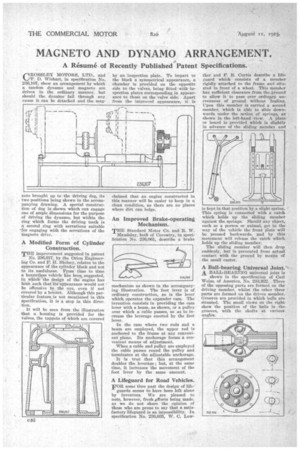
R 0 SSLE Y MOTORS, LTD.. and 14...JP. D. Wishart, in specification No. 236,107, show an arrangement by which a tandem dynamo and magneto are driven in the ordinary manner, but should the, dynamo fail through any. cause it can be detached and the rang
neto brought up to the driving dog, its • two positions being shown in the accompanying drawing. A special construction of dog is shown which can engage one of ample dimensions for the purpose of driving the dynamo, but within the ring which fornis the driving teeth is a secOnd ring with serrations suitable 'for engaging with the serrations of the
magneto drive.
A Modified Form of Cylinder Construction.
THE improvement suggested in patent No. 236,017, by the Orion Engineering Co. and P. H. Skelsey, relates to the appearance of the cylinder block and not to its usefulness. From time to time a bonnetless vehicle Was been suggested, in which the design of the engine has • been such that its appearance would not be offensive to the eye, even if not covered by a bonnet. Although this particular feature, is not mentioned in this specification, it is a step in this direction.
• It will be seen from the illustration' that a housing is provided for the valves, the tappets of which are covered by an 'inspection plate. To impart to the block a symmetrical appearance, a chamber is provided on the opposite side to the valves, being fitted with inspection plates corresponding in appearance to those on the valve side. Apart from the improved appearance, it is claimed that an engine constructed in this manner will be easier to keep in a clean condition, as there are no places where dirt can lodge.
An Improved Brake-operating Mechanism.
THE Standard Motor Co. and R. W. Maudslay, both of Coventry, in specification No. 236,061, describe a brake mechanism as shown in the accompanjing illustration. The foot lever is of ordinary construction, as is the lever which operates the expander cam. The invention consists in providing the cam lever with a beam, as shown, or a pulley over which a cable passes, so as to increase the leverage exerted by the foot lever.
In the case where two rods and abeam are employed, the upper rod is anchored to the frame at any convenient plane, Its anchorage forms a convenient means of adjustment.
When a cable and pulley are employed the cable passes round the pulley and terminates at the adjustable anchorage.
It is true that this arrangement doubles the leverage; but, at the same time, it increases the movement of the foot lever by the same amount.
A Lifeguard for Road Vehicles.
FOR some time past the design of life guards seems to have been left alone by inventors. We are, pleased to note, however, fresh efforts being made, as we do not share the opinion of those who are prone to say that a satisfactory lifeguard is an impossibility. In specification No. 236,035, W. C. Low
ther and Y. R. Curtis describe a lifeguard which consists of a member rigidly attached to the frame and situated in front of a wheel. This member has sufficient clearance from the ground to allow it to pass over .orclitipxY
evenness of ground without fouling. Upon this member is carried a second member, which is able to slide down-: wards, under the action of springs, as shown in the left-hand view. A plate' or board is provided which is slightly in advance of the sliding member and is kept in that position by.a slight spring. This spring is connected with a catch which holds up the sliding member against the springs. Should any object,: such as a person or animal, get in the way of the vehicle the front plate will' be pressed backwards, and by this movement will release the catch which holds up the sliding member.
The sliding member will then drop suddenly, but is prevented from actual: • contact with the ground by memis of. the small castor.
A Ball-bearing Universal Joint.• A BALL-DEARING universal joint is shown in the specification of Carl. Weiss, of America, No. 233,922. Three of the opposing parts are formed on the driving member, whilst the -other three. parts are formed on the driven member.Grooves are provided in which balls are situated. The small views on the right show the position of the balls in the grooves, with the shafts at various' angles.