


Patents Completed.
Page 62
If you've noticed an error in this article please click here to report it so we can fix it.
ROAD SPRINKLER.—Thwaite.—No. 13,551, dated 13th June, 1906.—This ap-paratns comprises a reservoir (a) beneath which is a furnace chamber (g) wherein is a grate (7). The reservoir is carried on wheels and beneath it are air pumps (1) ,communicating with a storage chamber .(j). The tar, or other substance, to be -distributed over the road-surface is fed 'from the chamber (j) by the pumps (1) through a conduit (k), and one of the pumps (1) also compresses air into the .chamber (a), so that a pressure is maintained upon the tar or pitch within the ,chamber. The tar, or other substance, is made liquid by the heat from the furmace, and is permitted, when desired, to flow from a feed pipe (v) to a sprinkler which sprays it over the road-surface. If desired, the apparatus may also carry a supply of sand to be fed by gravity, to a second sprinkler, whose discharge shall mingle with that of the tar, or it may be fed to this second sprinkler by means of air pressure. At the rear of the sprinkling
device, a brush (a.) may be carried, and to the rear of this a roller (5) may be trailed, so that the loose matter on the road surface is first thoroughly mixed with the tar, and then compressed by the passage of the roller. The pumps and the brush may be driven from the road wheels, and the .apparatus may be adapted for animal or motor power.
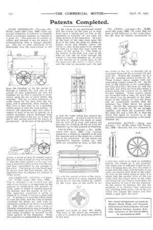
OIL-SAMPLING DEVICE.—F1 ()back. —No. 11,722, dated 10th May, 1906.— • This is intended to be lowered into the well of an oil-ship or storage tank for the purpose of ascertaining the amount of water, some of which is usually found at the bottom, and the quality of the oil. The apparatus comprises a casing or frame (6) in which is carried a glass tube (a). A spring (c) is provided which tends -to raise the tube, and the tube is further connected by levers (m) with rods (a) -carried by a plate (a) on which is a shackle (p). The plate (a) also caries valves (s) whereby communication may be made between the upper portion of the apparatus and closed chambers (q) situated in the lower portion of the apparatus. When Atte apparatus is suspended by the shackle (p), the valves (s) are maintained closed and the bottom of the tube (a) is kept down upon a sealing pad (2a) but, as the apparatus is lowered, oil can enter the upper portion of the apparatus. As soon as the base of the cage rests upon the floor of the tank, the plate (a), being released, drops and thereby opens the valves (s) and, at the same time, releases the tube (a) so that this rises under the action of the spring (c). The water at the bottom of the tank now rises in the tube (a) and the oil flows through the valves (s) into the chambers (q). As soon as the shackle (p) is pulled upon to lift the apparatus, the valves (s) again close, and the tube (a) descends upon the pad
so that the water which has entered the latter is trapped. A scale is placed beside the tube (a) whereby the depth of water can be read off at once, and means are provided for drawing off the oil from the chambers (q) for the purpose of sampling.
COUPLING.— Hensler. —No. 8,774, dated 11th April, 1906.—The coupling comprises a sleeve (a) adapted to fit over the opposite ends of the shafts (b, c) which are to be connected, In the sleeve are longitudinal tapered orifices (g), and these are connected by slots, or saw cuts (p, with the central orifices of the sleeve. When the sleeve is in place, tapered pins (h) are driven into the orifices (g), whereby the inner face of the sleeve is ex panded and made to grip the shafts. The ends of the sleeve are recessed at e and if to protect the projecting portions of the pins,
OIL LEVEL.—Lavaggi.—No. 13,308, dated 9th June, 1906.—In order that the level of the lubricant in the crank-chamber (B) may be readily ascertained by
the driver of the car, a chamber (A) is connected therewith by a conduit (C) and cock (D). Within the chamber (A) is a float (E), carrying contact pieces (G, H). These contact pieces engage with corresponding contact pieces (L, M). As the level of the lubricant in the crank-chamber rises and falls, the float (E) will rise and fall, and when the float falls below a certain level, the contacts (G, L) will be brought together. These contact pieces are connected with a lamp (N) and a bell (K) which may be situated on the dashboard of the vehicle, so that the driver will be immediately notified that the lubricant has fallen below the proper level. Should the lubricant rise abnormally, the contacts (H, M) are brought together, and these are connected with the lamp (0) and a bell (K) so that the driver will again be warned as to the quantity of lubricant existing in the crankchamber (13).
ANTI-SKID DEVICE.—Sharp and Another.--No. 25,531, dated 12th November, 1906.—Between the two elements of
a twin-tire, such as is used on motorbus wheels, two chains (a, 6) are mounted. The chains are of sufficient length to provide a hanging loop (d), but one chain is longer than the other, and the links of one chain are smaller than those of the other. As soon as the wheel tends to skid, it is stated that the smaller links of the one chain luck the larger links of the other and bring the two chains underneath the tread portion of one of the tire elements. As the chains lie between the two tire elements, it is obvious that, whichever way skidding takes place, one of the elements will engage the chains and thus obtain a grip upon the road.