


Patents Completed.
Page 36
If you've noticed an error in this article please click here to report it so we can fix it.
GEAR CASING.—Mann.—No. 9,738, April 26th, 1906.—This relates to casing for enclosing toothed gearing whereby the drive is conveyed from the transverse axle to the road wheel. On the end of the transverse axle (16) is a bevel wheel (15) which engages a second bevel wheel (11) on a longitudinal shaft (12).
Surrounding the bevel wheels (14, 15) is a divided easing (20). One portion of the casing is carried on a cylindrical member (21) which is supported by the transverse shaft (16) and also by the frame of the vehicle. On the other side of the casing (20) is a pin (24) which enters a bracket (25), also secured to the frame of the vehicle. The casing (20) is oil-tight and provides bearings for one end of each of the axles (16, 12). The other end of the axle (12) finds a bearing in a casing (6) carried on the wheel axle (2) ; this casing has a longitudinal extension which encloses the shaft (12). The casing (6) is bolted to a second casing (7) on the hub of the wheel, with which it forms an oil-tight joint. To remove the bracket (25), the side portion of the casing (20) can be readily removed and, if necessary, the shaft (16) can be taken out by removing the cylindrical member (21). Within the casings 8, 7) bevel wheels (13, 1) are mounted, whereby the drive is transmitted to the road wheel.
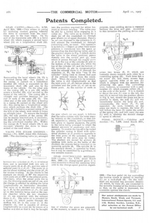
VALVE FOR STEAM ENGINES.— Shirley.—No. 3,947, dated 10th February, 1906.—The distributing valve (a), arranged
between two cylinders (b, bl), is of tubular form and is provided with two sets of
supply ports (d, d, di, and two sets of exhaust ports (e, e, i, el). The ports (d, e) are for ahead working and the ports (dl, el) for reverse working. As the cranks in the example are shown at 90" the respective inlet ports are at 180 to the exhaust ports. Obviously, when the ahead ports are in use, the reversing ports are out of use, and the change is effected by sliding the valve longitudinally as hereinafter described. The valve (a) is divided into three parts (g, hl) by the partitions (f, /1), the part tg) in this instance being used as the supply chamber while the two chambers {h, 121) are connected with the exhaust ducts (1, i1). The valve (a) is actuated by a sleeve (j), which passes through the stuffing box (4) in the cover (1) of the chamber (h), and is capable of sliding longitudinally on a rod (m) by means of a feather and slot so that it may be brought into the position required for either forward or reverse running. The valve may be slid by a forked lever engaging in a collar (x). The valve (a) is rotated by a shaft (m) off the crankshaft (v) through gear wheels (n) of equal diameter. Pistons (w, wl) are disposed in the cylinders (1, le) and actuate the crankshaft (v) through connecting rods, as usual. The operation is as follows :—Steam or other fluid under pressure is introduced into the space (q) surrounding the distributing valve, and in the position shown in Fig. 1 (which shows the valve in the ahead position) passes directly into the central part (g), from which it passes through the supply ports (d, 01) to the top of the cylinder (1) and to the bottom of the cylinder (61), while the top of the cylinder (0) and the bottom of the cyclinder (b) are in communication with the exhaust ducts (1., 11) through the chambers (h, h1), the term "top of the cylinder" being used to denote that part of the cylinder remote from the crankshaft. When the engine is to he reversed, the valve is slid longitudinally so that the inlet ports (dl, dl) deliver steam to the cylinders and the ports (el, el) act as exhaust ports. As the number of teeth in the gear wheel (n) are equal, it follows that the valve rotates with the same angular velocity as the crankshaft, an that cutoff, expansions, release, and compression, take place in regular sequence, the ports in the valve being arranged to attain the desired amounts of expansion and compression. To enable the cut-off to be varied the cylinder casing is fitted with cylindrical shutters (a) in positions opposite to the inlet ports of the cylinders, so that the width of the same may be varied. The shutters are moved by pinions (2) meshing with racks on the backs of the shutters, the pinions being mounted cn an operating spindle (3). The spindle (3) in the example shown, is operated by hand, but it may be controlled by a governor, in any suitable manner.
GEAR CONTROLLING MECHANISM.—Linley.—No. 7,717, dated March 30th, 1906.—In change-speed gears it is often desirable to throw the operating lever over to the change-speed position regard
purpose, some yielding device is required between the lever and gear. According to this invention the yielding device com prises two levers (E, F) which are normally drawn towards each other by a controlling spring (M). Each lever has a set screw (0) and these screws bear against opposite sides of an arm (L) which is integral with the member for advancing the gear. The controlling lever, however, is connected with a cammember (G) which engages rollers (II, J) on the ends of the levers. If it is desired to throw the arm (1) over to the left, the cam (G) is moved into the position shown in Fig. 2, but, should the gears not be in position to mesh, the arm (L) will not immediately follow the lever (E) and, consequently, the levers (E, F), arc separated. As soon, however, as the gears are made to register, the lever (F) will follow the lever .(E) under the action of the spring (M), and will carry the arm (L) with it, whereby the desired change of speed is effected.
PEDAL DEVICE. — Critchley and Another.—No. 7,188, dated March 28the
1906.—The foot pedal (A) for controlling the friction clutch is carried in bearings (C) on a rock-shaft (B). On the rock. shaft are mounted two eccentric sheaves
(D) which, by links (E), are connected to the movable member of the friction clutch so that, as the pedal is depressed, the eccentrics operate the clutch,