


Carburetter Action.*
Page 4
Page 5
Page 6
If you've noticed an error in this article please click here to report it so we can fix it.
By W. Morgan, B.Sc., and
E. B. Wood, M.A. (Cantab).
constant compositiou. I nees• —1.706s
tigations which had been
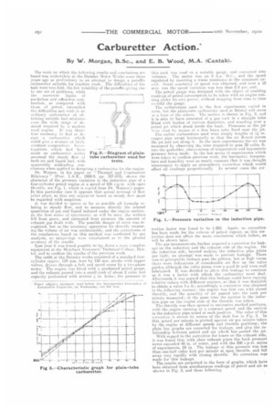
made on carburetter adieu Fig. 2.—Diagram of plainassumed the steady flow of tube carburetter used for both air and liquid fuel, with tests.
apparently misleading con clusions when applied to designing a carbine tter fir the engine. Dr. Watson, in his paper on " Thermal and Combustien Efficiency " (Proc. 1.A.E., 1908-9, pp. 387-4731. shows the character of the pressure variation in the induction pipe of a four-cylinder petrol engine at a speed of 656 r.p.m. with open throttle, see Fig. 1, which is et pied from Dr. Watson's paper. In this particular case it appears that actual reversal of flow takes place, so that any argument based on steady flow mast be regarded with suspicion. It was decided to ignore is far as possible all formulae relating to steady flow, and to measure directly the related quantities of gas and liquid induced under the engine suction. In the first series of eperiments, as will be seen, the writers fell from grace, and estimated from pressure the amount of exhaust gas dealt with. The possible danger of error was recognized, but, as the necessary apparatus for directly measuring the volume of air was unobtainable, and the correctness of the conclusions based on this method was confirmed by gas analysis, no misgivings were entertained as to the general accuracy of the results. Last year it was found possible to lay down a more complete equipment at the Merchaut Venturers"rechnical College. Bristol. and to confirm the results of the previous work. The outfit at the Daimler works consisted of a standard fourcylinder engine, 124 mm. bore by 150 mm. stroke with tappet valves, driven through a belt. and speed cones by a two-Phase motor. The engine was fitted with a graduated petrol gauge, and the exhaust passed into a small tank of about 2 cubic feet capacity perforated with several in. holes; the pressure in
this tank was read on a suitable gauge, and teniverted into volumes. The motor was an 8 h.p. 1).G., and the speed regulated by inserting a water resistance in the armature circuit. Great constancy of speed was obtained, and over a 10 Olin. run the speed ,etriation was less than 0.4 per cent. The petrol gauge was designed with the object of enabling readings of petrol consumption to be taken with an engine running under its own power, without stopping from time to time to refill the gauge. The carburetters used in the first experiments varied in ion», but the plain-tube carburetter used at Bristol will serve AS a type of the others. The section is shown in Fie. 2, and it is seen to have consisted of a gas cock ie a straight tubes fitted with bushes of various diameters, and standing over a petrol jet which stood inside the bush. Pressures at. the jet were read by means of a fine brass tube fixed near the jet. The earlier carburetters used were simply lengths of 14 in. (sipper pipe swept horizontally so that the air flowed across the jet and not along it. In the later experiments the air was measured by observing the time required to pass 30 cubic ft. into the gasTiolder, observations of temperature and barometric pressure being made. In the last series of experiments which were taken to confirm previous work, the barometer, temperature and humidity were so nearly constant that it was thought unnecessary to apply an atmospheric correction which would
affect all readings proportionally In several cases the car
rection factor was found to he 1.005. Again, no correction has been made for the volume of petrol vapour, as this car rectio» does not affect the main conclusions which follow, as will be shown later.
The gas measurements further required a correction for leakage on the induction and the exhaust side of the engine. On the induction side, beyond making the induction pipe joints gas tight, no attempt was made to prevent. leakage. There was no perceptible leakage past the pistons, but at high vacua there were indications of considerable air flow up the valve guides, although the valve stems were a good fit. and were well lubricated. It was decided to allow this leakage to continue as it was a factor with which the carburetter must deal. Afterwards it was argued that this leakage could have varying relative values with different engines, so that. it was desirable to obtain a value far it; accordingly a correction was obtained in the following manlier: the engine was first run with closed throttle, and the quantity of air passed into the lank per minute measured ; at the same time the suction in the induction pipe on tho engine side of the throttle was taken.
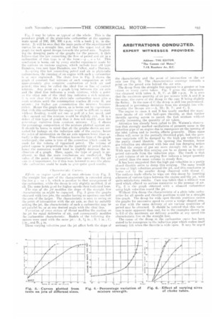
The throttle was then opened to successive marked positions, with the engine running at a constant speed, and the suction in the induction pipe noted at each position. The value of this correction is shown by means of the dash line in Fig. 3. In this, petrol per minute is plotted against air per minute taken by the engine at different speeds and throttle pusitions ; the plain hue graphs are corrected for leakage, and give the relationship between petrol and air which has passed the jet. With regard to the correction for losses on the exhaust side, it was found that with clear exhaust pipes the back pressure never exceeded 48 in. of water, and with the 500 r.p.m. series of experiments, 24 in. The leakage at this pressure was less than one-hall cubic foot per minute at open throttle, and fell away very rapidly with closing throttle. No correction was made for this leakage. The results are presented in the form of graphs, which have been obtained from simultaneous readings of petrol and air as shown in Fig. 3, and those following.
3 may be taken is typical uf the whole. This is the petrel-air graph of the plain-tube carburetter at the approximate speed of 250, 500, 900 r.p.m. with a bush g in. in diameter. It will be seen that the main parts of the superimposed curves lie on a straight line, and that the upper end u the gtaph for each speed droops towards the petrol axis. Neglecting the drooping parts of the graphs for the present, it thOrt follows that the law connecting the flow of petrol and air in a carburetter of this type is of the form :--y b.r. This couclusion is borne out by every similar experiment made by the authors on various engines, which include four old type Daimlers. two new type Daimlers, one Talbot, and it Harracq. At cola iug this law connecting petrel And air in plain-tube earburetters, the running of an engine with such a carburetter is at mit"explained. The chain line in Fig. 3 shows the
graph of constant fuel in of sneh composition as will appreximately give complete combustion of both air and
petrol; this may be called the ideal line of correct mixture. Any point on a graph lying between the air axis and the ideal line indicates a weak mixture, while ti point on the other side of the ideal line indicates a rich mixture. 11 is. now clear that, this plain-tube carburetter must give a \veal: mixture until the consumption reaches 30 cuMe ft. per utintitt, : for higher gas consumption the mixturo becomes richer. Hence the graph shows, as is borne out by experience, that with this carbnretter the engine would be diffieult to start. withem flooding, would not run or pull at a low sliced, and wht e opened out the mixture would be slightly rich. It is a defect of this type of graph that it dues not readily show the percentage. va.riatitiu from constant inixtu re Fig. 4 ehews the percentage composition of the mixture plated against air. It sheuld be borne in mind that all the graphs shown are corrected for leakage on the induction side of the engine. hence the point, of intersection on the air axis appears lower than actually is tile case. This correction leaves the type of the graph Unehanged; the same is true of the correction which could be made for the volume of vaporized petrol. The volume of petrol vapour is proportional to the quantity of petrol taken, hence the correction would tend to slightly decrease the inclination of a. graph. Here, again, the type of graph is unaltered, so that the main conclusions are unaffected. The value of the point of intersection of the curve with the air axis is of importanre. for if this were lowered to zero the plain'tile. carburetter could be made to give quite good results.
Cho 11 aeridtic Cur ff.+ .,1.0'0(1 are at once obvious froIll Fig. 3. The straight line part a the characteristic is extended along the line y = ox b, which is peculiar to that arrangement of the earburetter„ while the droop is only slightly meddled, if at all. The same holds good for higher speedy than indicated here. The size of the jet modifies the slope of the straight line aharacteristic as might be expected. Fig. 3 gives the graphs obtanted with two jets, the smaller having an aperture one-half the area of the larger. The characteristic is seen to swing on the point of intersection with the air axis, so that by suitably setting the jet, the characteristic of such a carburetter may be set parallel to, or at any desired anglø with the ideal line.
Voriation of cross section of throat modifies the suction on lie jet for equal deliveries of •air, and consequently modifies he carburetter characteristic. Bushes of the following diameters were used with the same jet :A, I iii. II, 1 in. ; C,
in., and D, in.
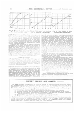
Those varying velocities past the jet affect both the slope of the characteristic and the point of iutersection ■ni the air axis (see Fig. 6). The characteristics converge towards a point on the petrol axis behind the air axis.
The droop from the straight line appears to a greater or less extent on every curve taken. Fig. 7 gives the characteristics obtained with tubes A, Ii, C. at 500 rpm. It is seen that the maximum quantity of air per minute with A and B is the same, the curve of the droop in the curse 14 being slightly the flatter. In the case of C the droop is still less ;Jammu-iced. Measured in percentage deviation from the straight line relationship the droops are :—A, 23; B, 7; and C, 5.
The engine in cases .A and 13 has nearly reached the maxi mum intake of air with half-open throttle, so that further throttle opening serves to enrich the fuel mixture without greatly increasing the quantity of air taken. Attention has already been called to Dr. Watson's observation that strongly marked oscillations of pressure occur in the induction pipe of an engine due to resurgence on the opening of the inlet valves and to inertia effects generally. These same effects will occur in the partially-throttled pipe, but the pressure variations will be damped by the high gas velocities at the partly closed throttle. On opening the throttle, lower gas velocities are obtained with less and less damping action so that the surges of gas are more atrongly felt at the jet. With open throttle this surging can he so strong as to carry petrol outwards from the induction pipe. 'The result is that a unit volume of air in surging flow induces a larger quantity of petrol than the same volume in steady flow. It has been suggested that the high gas velocities iii a partly closed throttle serve to damp this surging, The same would be true of high velocities around the jet, and this conclusion is larrne out by the smaller droop observed with throat C. The authors made efforts to wipe out this droop by inserting silencers of various types between the engine and the jet,with quite satisfactory results. Care was taken that a silencer was used which offered no serious resistance to the passage of air. Fig. 8 is the graph obtained with a silenced carburetter using high velocities round the jet. Without this droop the characteristic of a litain tube carburetter for all speeds and throttle positions would be a straight line graph. The droop fur wide open throttle positions causes the graphs for successive speed to cover a wedge shaped area, so that with the same delivery of air various quantities of petrol may be obtained. It should be noticed that this variation is more apparent than real, for in the examples shown, up to 0.8 of the maximum air delivery possible at any speed the characteristic lies on the straight line.
The cause of the droop in the carburetter curve has been stated to be resurgence in the inductiou pipe which makes itself seriously felt w hen the throttle is wide open. It may he urged that the droop may be caused by a change in the type of air flos ! set up at certain conditions of velocity and throat area. If this were so it would be expected that the characteristics obtained at different speeds with the same bush would all show the graph falling from the straight line at the same point. Reference to the superimposed curves obtained with the same hush at speeds of 300, 5(X) and 900 r.p.m. (Fig. 3) shows that the droop begins to be apparent at points indicating different velocities with different speeds.
Variation in. back pressure may be expected to affect the characteristic, for in general, the pressure in the cylinder, on the opening of the inlet valve is greater than that in the induction pipe, so that a rush out of the cylinder takes place. setting up surging (see Fig. 1). This effect will be the greater. the greater the back pressure; and as a consequence it may be expected that other things being equal a high back pressure will give a carburetter characteristic with a greater droop than that obtained with a. low back pressure. This is brought out in Fig. 9, which shows characteristics obtained with normal back pressure, and with a pressure of 5 lb. per sq. in.
Number of Cylinders.
The adjustable tappets on the valve lifters of the engine were removed first from the two back cylinders leaving the two front ones in action. Afterwards the third cylinder tappets were removed. In this way characteristics were obtained with two cylinders and with one Cylinder in action. The type of characteristic remains unchanged.
Carburetter Characteristics as a Guide to Carburetter Design.
The characteristic of a plain-tube carburetter for all speeds has been shown to be a straight line (neglecting droop). The slope of this graph may be varied to any degree by selecting a suitable jet. Let the jet be adjusted so that in a given plain tube carburetter the characteristic lies parallel with the ideal line. The mixture delivered is now weak all along the line. very weak at first, and becoming very nearly correct for large consumptions of air. Another way of stating this, is to say that in such a plain-tube carburetter there is a. constant short age in the delivery of the liquid. This being so, the designing of a constant mixture carburetter is within reach of attainment; allow the constant shortage to dribble into the induction pipe and the problem is solved, except for questions of convenience, The droop on the characteristic for any given speed does not necessarily lead to waste of petrol, for the graph may be set so that the terminal points of the characteristics be parallel to the ideal line; a suitable constant supply then enables the ideal mixture to be obtained at all open throttle positions. At intermediate throttle positions the mixture would be weak, but if the statement be accepted that such weak mixtures are economical this would be a desirable feature. In any event when maximum torque was required at any speed the reouired mixture could be obtained by fully opening the throttle; with throttled positions maximum torque is obviously not required, and some weakness of mixture would not be felt.
To sum up, there appears to be no necessity in any carburetter for extra air devices, or the multitudinous contraptions employed, other than a neat form of apparatus for supplying this constant extra supply of petrol.
It may he objected that the foregoing results have been obtained under conditions which do not occur in practice. This is true, and to estimate the effect of actual running conditions in modifying the characteristics obtained by driving the engine by an electric motor, measurements of air and petrol consumption have been taken with the engine running under its own power. The apparatus employed was the same, except that the electric motor was cut out and replaced by a rope brake. The engine speed was held constant for various throttle openings by varying the load on the brake, and then readings of air arid petrol were taken as before. The results obtained bore out completely those obtained by driving the engine by an electric motor.
Characteristics of Typical Carburetters.
Several carburetters were examined in the same way as the plain-tube carburetters, and their graphs plotted.
fwe hop,,, to reproduce.a few of the graphs thus obtained in oar next