


A SELF-COOLING ENGINE..
Page 32
If you've noticed an error in this article please click here to report it so we can fix it.
A Resume of Recently Published Patents.
THE title of this week's page for patents must inevitably be rather intriguing. We are acquainted with air cooling, with water 'cooling and -with various modifications of the application of these two main principles. Selfcooling requires some explanation, and none the less bemuse the design of the engine embodying it originates in India, where, so far as the popular conception of that country goes, more than elementary methods of cooling are generally regarded as being desirable.
We extract the term from patent specification No. 214,697, for which G. D. Westropp is responsible. In that specification there is described an inven tion which has for its object the provision of an improved construction of engine which will be self-cooling without requiring 'water cooling equipment.
The principal and outstanding characteristic of this novel power unit is the employment of a six-stroke cycle as against the familiar four-stroke or Otto cycle, or the hardly less-known twostrOke. The six strokes consist of induction, compression, explosion and exhaust, followed by two more, which are employed in introducing to the cylinder, and expelling therefrom, 'a charge of air or gas which Serves to effect the cooling of the cylinder and piston. This cooling charge may be composed of air drawn directly from the atmosphere, of air laden with oil spray or vapour drawn from the engine crank. chamber or of carburetted air. In the last-named case the charge is compressed, on expulsion from the cylinder, into the induction 'pipe or some other convenient place, where it is retained under pressure in readiness for admission to the cylinder on the subsequent induction stroke.
Apparently, therefore, this so-called self-cooling system is,. after all, as might
BIG
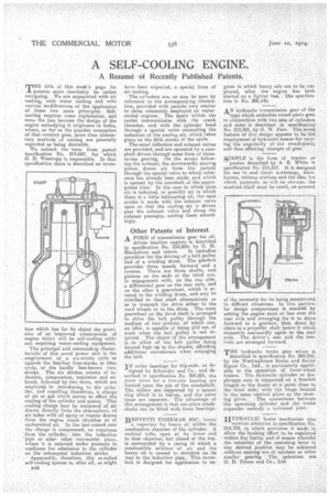
have been expectod, a special form of air. cooling. • The cylinders are, as may be seen by reference to the accompanying illustration, provided with jackets •very similar to those commonly employed, on watercooled engines. The space within the jacket communicates with the crank chamber, and with the cylinder head through a special valve controlling the induction of the cooling air, which takes place on the fifth stroke of the cycle.
The usual induction and exhaust valves are provided, and are operated by a camshaft driven through some form of threeto-one gearing. On the stroke following the exhaust, the downwardly moving piston draws air from the jackets through the special valve to which referi ence has already been made, arid which is opened by the camshaft at' the appropriate time. In the case in which pure air is inducted, or possibly air in which there is a little lubricating oil, the next stroke is made with the exhaust valve open so that the cooling air is driven past the exhaust valve and along the exhaust passages, .cooling them accordingly.
Other Patents of Interest.
A FORM of transmission gear for oildriven traction engines is described in specification No. 214,835, by G. M. Blackstone and others. It embodies provision for the driving of a belt pulley and of a winding drum. The gearbox provides three speeds forward and a reverse. There are three shafts, and pinions on the ends of the third one, in engagement with, on the one side, a differential gear on the rear axle, and on the other a gearwheel, which is secured to the. win-ding-drum, and may be clutched to that 'shaft alternatively so as to transmit the drive either to the road wheels Or to the drum. The main gearwheel on the third shaft is arranged to drive the belt pulley through the medium' of two pinions, of which one, an idler, is capable of being slid out of mesh when the belt pulley is not re-. quired. The object of the arrangement is to allow of the belt pulley being located high up in the chassis, affording additional convenience when arranging the belt.
IN roller bearings for big-ends, as de signed by Schneider and Co., and described in specification No 204,021, the inner races for a. two-row bearing are formed upon the pin of the crankshaft. The rollers are separated by a spacer ring which is in halves, and the outer races are separate. The advantage of this arrangement is that one-piece crankshafts can be fitted with these bearings.
BR.EVETTI UGHEMAR SOC. locate
a vaporizer for heavy oh within the combustion chamber of the cylinder. A vertical tube, open at its lower end to that chamber, hut closed at the top, is surrounded by a casing in which a combustible mixture of air and the heavy, oil is caused to circulate on its way to theincluction pipe. This invention is designed for application to en
gines in which heavy oils are to be em:ployed, after the engine has been started on a lighter fuel.. The specification is No. 206,146.
AN hydraulic iransmission gear of the type which embodies awash-plate gear . in conjunction with two sets of cylinders and rams is described in specification' No. 214,501, by G. W. Parr. The novel feature of this design appears to be the employment of hydraulic means for varying the angularity of the swash-plate, and thus effecting changes of gear.
SIMPLE is the form of tractor or
pusher described by A E. White in specification No, 214,517. It is designed for use in and about workshops, warehouses, railway stations and the like, tor which purposes, as will be obvious, the machine itself must be small, on account
of the necessity for its being manceuvred in difficult situations. In this particular design compactness is ensured by setting the engine more or less over the rear axle and arranging for it to drive forward to a gearbox, then down by chain to a propeller shaft below it which transmits nearwardly again to the rear, axle. The driver's seat and the controls are arranged forward.
THE hydraulic brake gear whicn is described in specification No. 204,310, by the Westinghouse Brake and Saxby Signal Co., Ltd., is particularly applicable to the operation of front-wheel brakes. The hydraulic cylinder or diaphragm case is supported on a bracket hinged to the frame at a point close to' the front axle, with the hinge located in the same vertical plane as the steer ing pivot. The connections between the operating cylinder and the brake expander embody a universal joint.
IIYDRAULIC brake mechanism also
receives attention in specification No. 214,739, in which provision is made to allow the braking effort to be regulated within Brie limits, and of means whereby the retention of -the operating lever in any desired position may be achieved without. making UPS of ratchets or other similar gearing. The patentees are G. D. Peters and Co., Ltd.