


REAR-AXLE DESIGN.
Page 34
If you've noticed an error in this article please click here to report it so we can fix it.
A Résumé of Recently Published Patents.
The principal advantage which is claimed for the rear axle described in specification numbered 149,333 is that it is light and that, in consequence, its employment redness the unsprung weight on the...vehicle to which it may be fitted. It is stated to be suitable alike for lorries and tractors, and is shown, in the drawings which accompany the patent specification, as applied to the latter type of vehicle. The transmission gear is of the double-reduction type, of the -kind in which the final reduction is by gearing within the road wheels. The principal features of interest are in connection with the mounting of the final-drive gears within the wheels, and it is to that part of the invention that we propose to devote ourselves in this refeience.
The differential gear is carried in a central casing, in the usual position on the axle, and the same casing also serves to cover the first reduction gear, which is by bevels. Two tubular extensions are bolted to the central case. They differ from the usual type of axle tube in that they are bell-mouthed at their outer ends. The stub axles, on which the road wheels 11111, are spread-eagled on their inner ends, so that they will conveniently bolt to the bell-mouthed end of the axle tubes, and at the same time not interfere with the driving gears. The axle shaftsiare central with the wheels, and each carries a pinion oathe outer end. The shafts are supported' in roller bearings in the end of the axle tubes, and also by outboard beariugs, which, in the die wings, are shown as ball bearings. The,enlarged ends of the axle tubes, besides gserving as supports for the stub axles; also carry spindles on Which are mounted idler wheels, which intervene between the driving pinions and the internal gear rings which are bolted to the road wheels. Suitable provision is made for enclosure of all the driving mechanism. A feature is made of accessibility to the .lifferent gears. The patentee is Auto Motive and Accessory Export Co., Int%
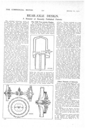
The Still Two-stroke Engine.
An interesting design of two-stroke engine is described in specification No. 171,838 by W. J. Still. The patentee points out that in two-stroke engines of the valveless type it has hitherto been regarded as necessary that the exhaust port should be so designed and located, relative to the inlet port, that it is uncovered by the engine piston slightly before the inlet port is uncovered to admit the scavenging air charge, and, of course, closes after the inlet port has closed. It follows aa.a consequence that after the inlet port has closed, there is an escape of some portion of the air charge within the cylinder, the charge escaping until the exhaust port has also closed. The effect of this is to reduce the weight of the charge within the
cylinder. Various methods have been tried, from time to time, to counteract this; for example, the pressure of the scavenging air has been raised above the normal by extraneous means, and in another cue the exhaust gas was throttled in the pipe leading from the cylinder. The principal .object of the present invention is to provide means of ensuring .a full charge to the cylinder, and it is achieved as follows :— The inlet and exhaust ports are so arranged that the inlet port Is uncovered by the piston prier to the uncovering of the exhaust port, and is closed by the jiiston after the closure of the exhaust port. There is, however, a mechanically operated release valve provided for the exhaust, so arranged that it lowers the pressure within the cylinder at the end of the expansion stroke prior to the uncovering of the main exhaust ports.
AS will be noted on reference to the accompanying drawing, there are three sets of ports to the cylinder. That on the left is the inlet port. On the right the lower set is the main exhaust port, while the upper set is the auxiliary one, controlled by the piston valve shown, which is driven by some convenient part of the engine. During the expansion stroke of the engine the mechanical release valve opens, so that when the piston passes the upper row of ports the gases escape, and the pressure within the cylinder rapidly fails to the same as that of theatmosphere, or even slightly below it. The inlet port opens next ; and subsequently the main exhaust port, and scavenging takes place in the usual way. The mechanical release valve is closed, and also the main exhaust port, prior to final closure of the inlet port, so that a rise of pressure in the inlet pipe occurs just before the closing of that port. It follows that the charge within the Ruder will be the full swept volume of the cylinder.
Other Patents of Interest:
Details of the Madison-Kipp oiler are given in specification No. 155,277. The invention is mainly concerned with the details of the manufacture of the cup, which, as regards its principle of operation, is fairly well known to our readers.
L. Renault proposes to limit the maximum speed of a motor vehicle by fitting an extra set of brake shoes, which take effect automatically, under the influence of centrifugal force, immediately the speed of the vehicle passes a predeter mined limit. The patent is described in specification No, 167,442. An *ingenious petrol consumption recorder is the subject of a patent which is described in specification No. 171,797, by H. J. Turner. It is applied to the fuel tank, and consists of two sets of mechanism of the float and Archimedean screw type.
No, 155,770; by M. Parker, describes a form of safety hitch for use in connection with a motor tractor .and implements. It consists, in the main, of a hinged jaw. An engine governor, mainly applicable to the Foedson tractor power unit, is thb subject of specification No. 171,794, the patentee being F. G. G. Armstrong.